The early proponents of the Erie Canal were a remarkable group. Jesse Hawley, Elkanah Watson, and Gouverneur Morris showed great imagination — and risked being labeled as madmen — when in the early 19th century they individually proposed constructing an artificial river from the Hudson to the Great Lakes.
Hawley — a grain merchant with no advanced education — accurately predicted the canal’s route and final cost in a series of essays written while serving time in a Canandaigua jail for bankruptcy.
But these men were not engineers, and one detail they initially could not grasp was how, exactly, the canal would surmount the 568-foot difference in elevation between tidewater and Lake Erie. The general consensus was that the canal would be constructed as an inclined plane that gradually descended as it made its way, west to east, across the state.
The heavily glaciated terrain of New York state presented a serious obstacle to this plan. The canal would have to cross several rivers and valleys, including the wide, flat bowl of Cayuga Marsh. Enormous embankments would be needed to maintain a consistent slope across all of these elevations, and the mere thought of constructing these eventually made it clear that the whole idea was, well, crazy.
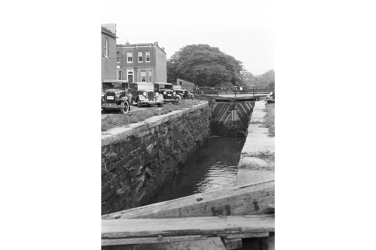
A more practical solution was the miter gate lock, invented in the late 15th century by Leonardo da Vinci.
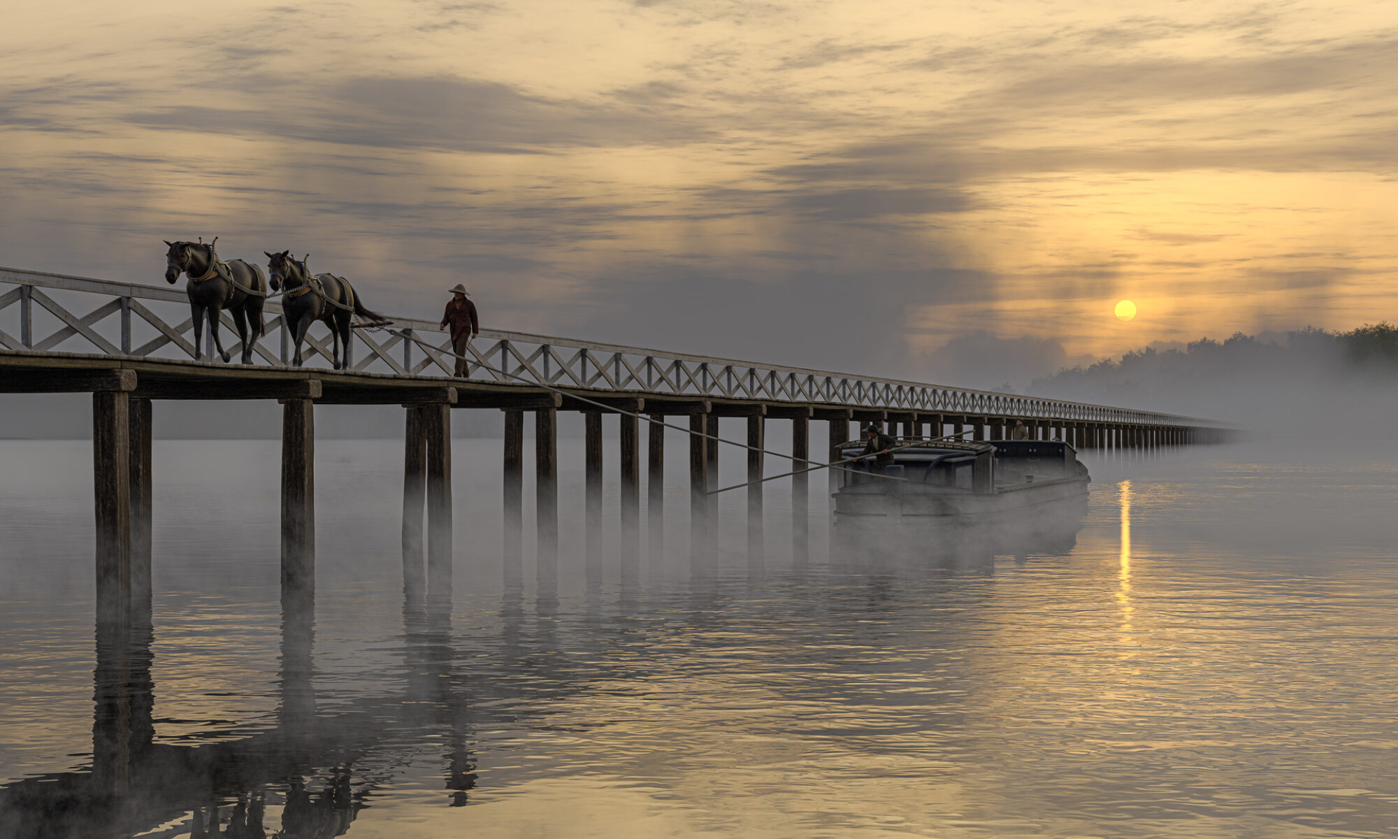
A canal lock is basically a long chamber, large enough to accommodate a ship, boat, or barge, with a watertight gate on each end. After a vessel enters the chamber the gate behind it is closed and the water level inside is raised or lowered as needed. Then the other gate is opened to allow the vessel to continue on the new level.
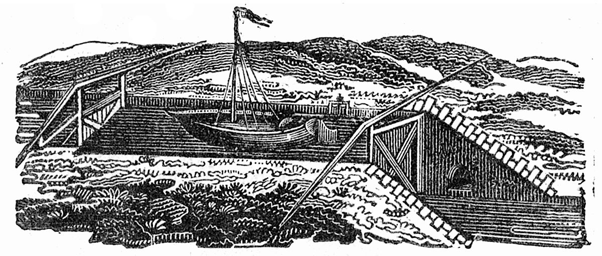
The principle of the canal lock had been known for some time, and various types of gates had been used with varying degrees of success. Da Vinci’s innovation was simple but brilliant. The inside frames of his lock gates were mitered so that, when closed, the gates formed a V with the point facing the upper water level. The pressure of the water against the V forced the gates together, ensuring a tight seal.
Da Vinci’s design subsequently was used throughout Europe and for canals in the United States, including the Erie Canal. It is still used on canals today.
By the time work began on the Erie Canal, American engineers had already mastered the basics of lock construction, by trial and error, on earlier projects such as the Middlesex Canal in Massachusetts and the canals of the Western Inland Lock Navigation Company. Both wood and stone had been used as building materials. Over the years the many problems encountered with wooden locks convinced the Erie engineers that all of their locks should be built of stone, despite the higher initial cost.
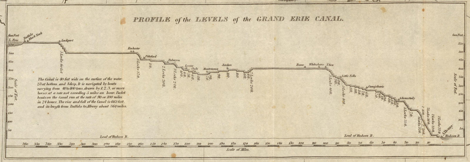
In all, 83 locks with an average lift of eight feet would be built to lift the canal from tidewater at Albany to Lake Erie at Buffalo. The difference in elevation was 568 feet. But the descent at Cayuga, and a smaller one near Syracuse, increased the total rise and fall to 692 feet.

The standard lock chamber size on the first Erie Canal was 15 by 90 feet, which could accommodate vessels 78½ feet long by 14½ feet wide. Most locks had a vertical lift of eight feet (or less), though some had lifts of 9 or 10 feet and, in the case of the famous flight at Lockport, 12 feet.
In a few locations, such as Lockport, the lock chambers were excavated out of solid rock. In others they were anchored directly on underlying bedrock. But in most places the bedrock was too deep and out of reach. There, hundreds of piles would be driven. On top of those a timber raft or mat would be laid and reinforced with planking. On top of this the stonemasons would construct the walls of the lock chamber.
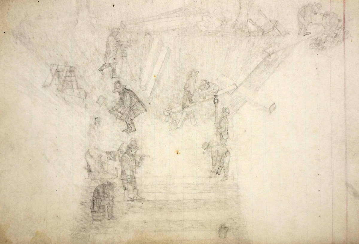
The process of building a lock was outlined in an 1826 proposal submitted by contractor David Fitzgerald to the canal commission:
“I propose to construct the Lock which is required on the Eastern section of the Erie Canal near Waggoner[’]s for the consideration of nine hundred dollars a foot lift, of the finding all materials . . . to the excavating the pit, piling and preparing a solid foundation, quarrying cutting and laying the masonry and completing the wood and Iron work and embanking puddling [and securing] the Lock. . . . The Lock to be fully completed in the month of September. . . . Lock 8 foot lift”
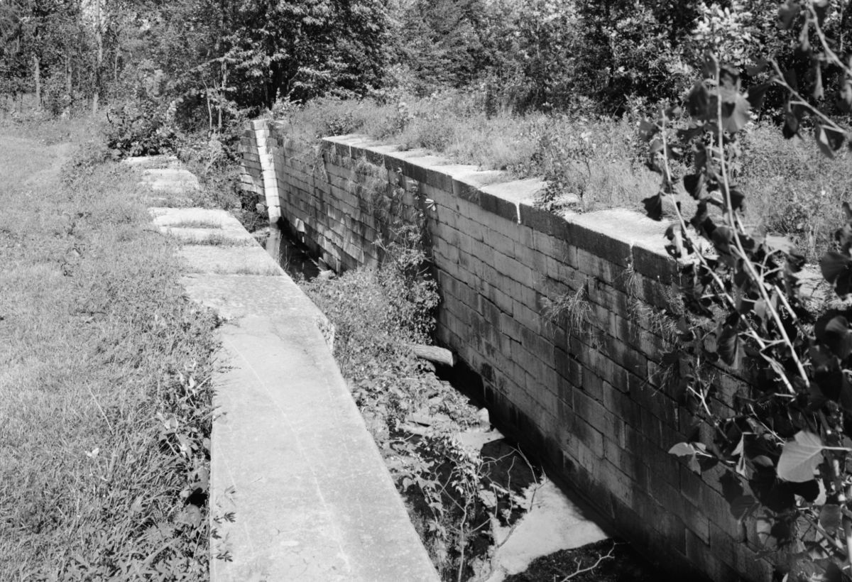
Lock chamber walls were constructed of dressed stone, often quarried locally. For mortar, the masons initially used quicklime but soon adopted a new, much superior hydraulic cement developed by canal engineer Canvass White.
The stonemasons were craftsmen and they built things to last. But time and subsequent development have taken their toll. The remains of several 19th-century Erie Canal locks survive across New York state, but nearly all date from the First Enlargement, 1834–1862, or later. Surviving locks from the original canal are rare, so we have few direct references that can be used to help us create an accurate digital model of an original Erie Canal lock.
Fortunately, there are good, surviving examples of locks from other canals of the same period and a few contemporary drawings that we can turn to.
Two other canals in particular can provide the information we need.
Construction of the Chesapeake & Ohio Canal began in 1828, a little over two years after the opening of the Erie Canal. It originally was planned to extend from Washington, D.C., to the Ohio River at Pittsburgh. But in 1850, after years of delays, labor unrest, and cost overruns, construction ground to a halt at Cumberland, Maryland.
Despite the fact that it was never truly completed, the C&O proved to be an efficient way to move coal from the Allegheny Mountains to the East Coast, and it remained in operation until 1924.
The C&O canal prism and locks were built to dimensions similar to those of the Erie Canal. But unlike the Erie Canal, the C&O was never enlarged. Many of its original structures remain in good condition and have been carefully documented by the National Park Service. Photographs, plans, and reports created by the service’s Historic American Buildings Survey (HABS) and Historic American Engineering Record (HAER) are kept at the Library of Congress, and most are available online.
Much the same is true for the Ohio and Erie Canal, constructed from 1825 to 1832 to connect Lake Erie at Cleveland to the Ohio River at Portsmouth. Although most of the Ohio and Erie has not survived, sections of it have been preserved and documented by the park service.
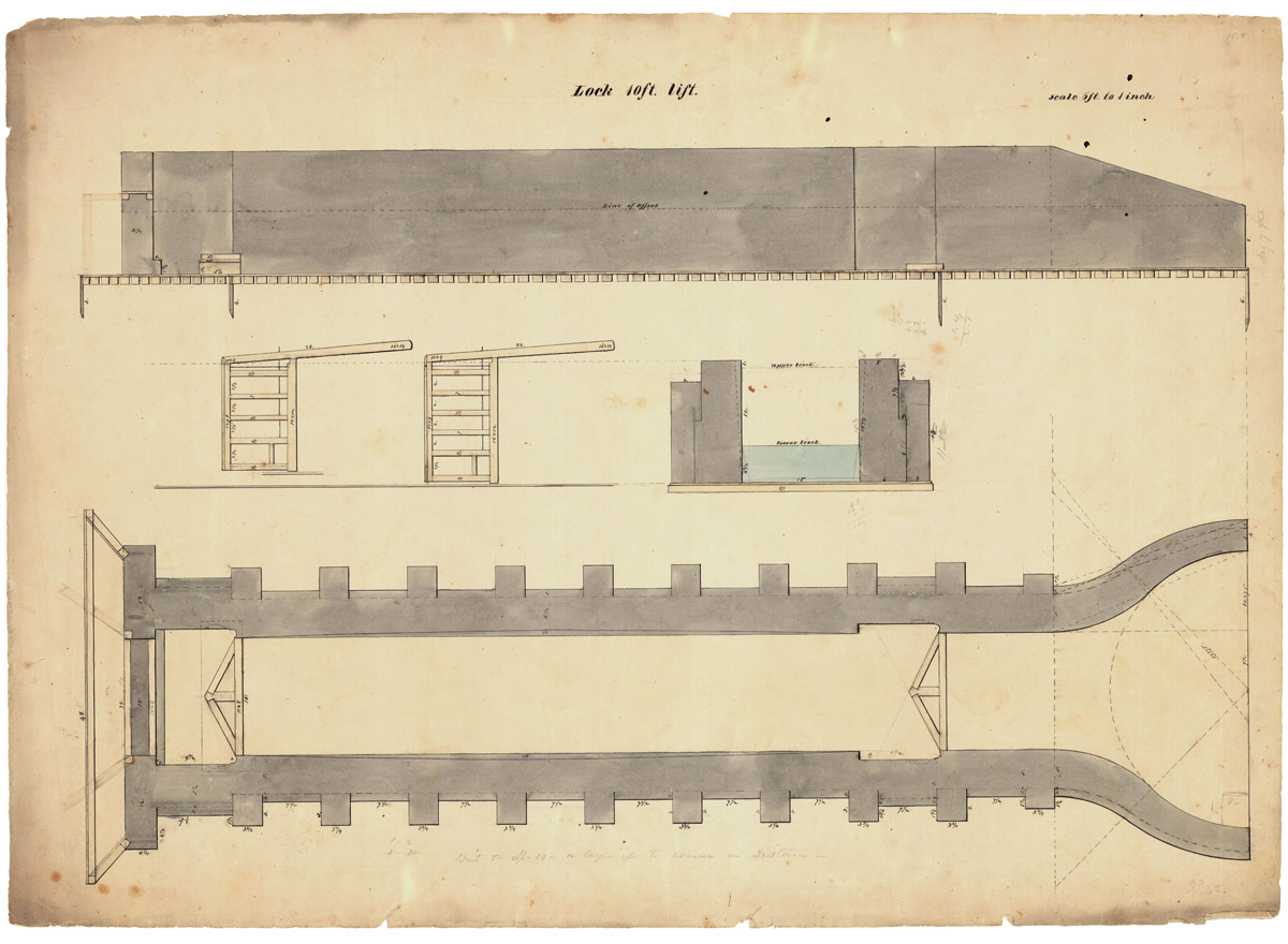
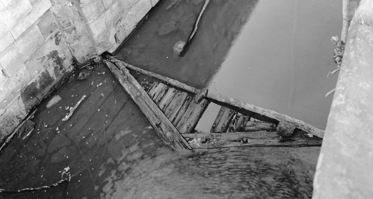
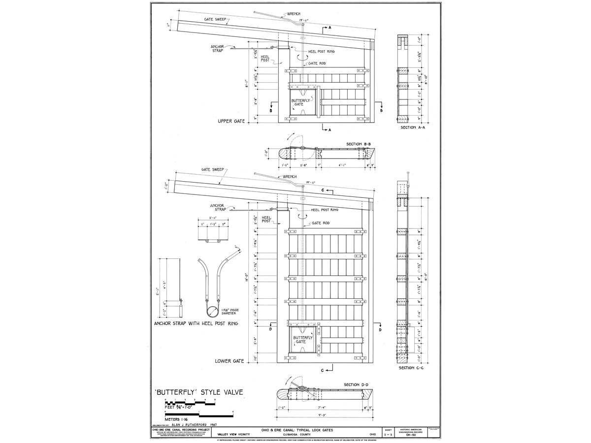
My digital lock model is based primarily on a plan and elevation drawing found among the papers of Erie Canal engineer John B. Jervis and preserved at the Jervis Public Library in Rome, New York. (Another drawing from this collection served as the basis of a digital model of the Little Falls Aqueduct.) The drawings show a lock of 10-foot lift, but it is easily adapted to fit the more usual 8-foot lift.

The model includes many details that will be hidden — below ground level or under water — when it is placed in a scene. These include the counterforts, buttresses that helped support the stone chamber walls; miter sills, which supported the lock gates when they were closed; and the gates’ butterfly valves, which were opened and closed by turning iron handles referred to as “keys.”
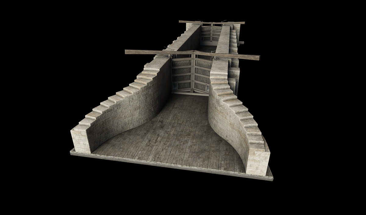
Once the model is finished, surface detail and color are added in Substance Painter. Two copies of this model will be placed in the Little Falls scene to represent original Erie Canal locks 44 and 45.
Steve, Just read your article. That is a really cool digital model of a canal lock. I see it must be part of another project. I will look at those posts later. Really interesting.
Thanks, Tom. Nice to hear from you. Each step teaches me a little more. It really is interesting, and cool to live in an area with such a rich history.
Steve! Now we know what’s you’ve been up to. Excellent work! I’ve been working in Blender for about a year now. Nice to see these models!