The mystery of the missing pumps, part two

De Re Metallica
Georgius Agricola’s richly illustrated “De Re Metallica,” published in 1556, describes various types of pumps in great detail. (University of California Libraries via Internet Archive)

The origins of the lift pump, like those of many other indispensable inventions, are lost somewhere in the distant past.

The principle behind the pump’s operation — atmospheric pressure — was not discovered until the 17th century. But by then lift pumps had already been in use for generations. For miners and seamen, especially, they had long been an essential part of everyday life.

Some time ago I began working on a scene to show workers digging the Erie Canal through Cayuga Marsh. The scene needed to include the hand-powered pumps they used to get rid of the water that constantly seeped into the excavation. I made some preliminary inquiries and could not find a source that could tell me what those pumps looked like. (Maybe no one knows.) So I decided to dig deeper.

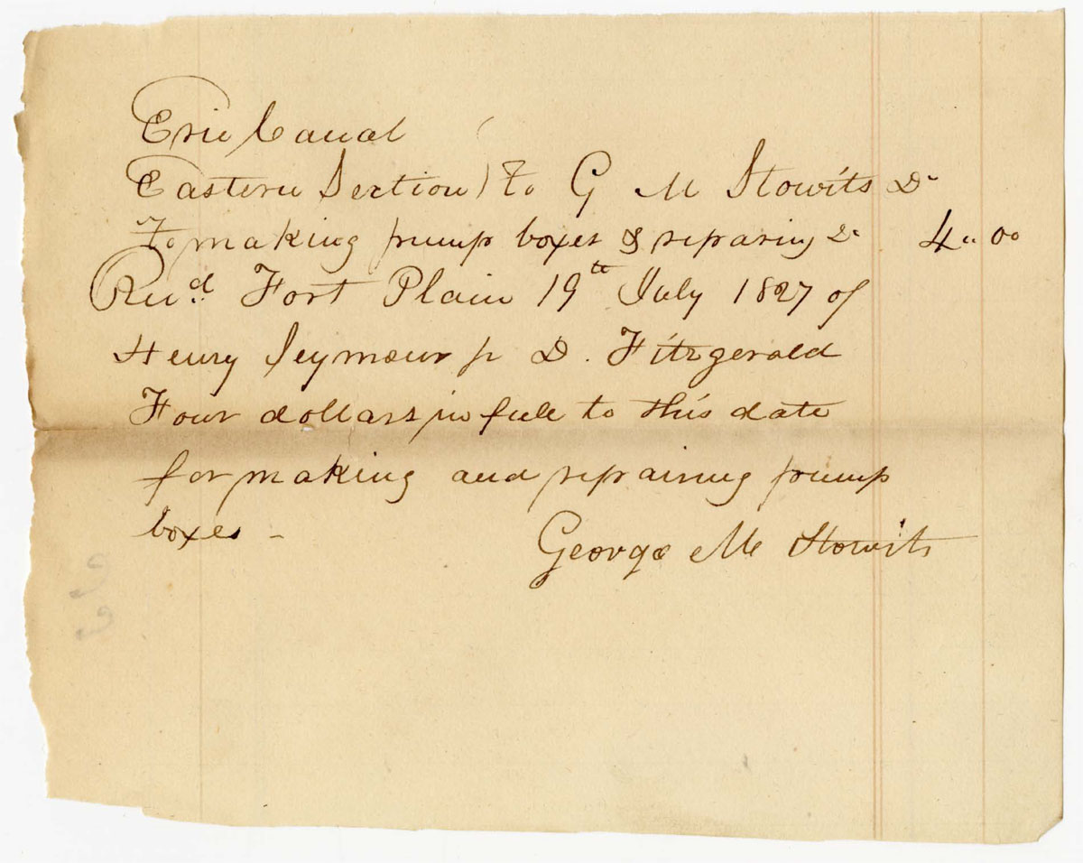
In part one, we combed through contractor receipts for clues. This part will show what I’ve learned from the broader technical record, as presented in contemporary documents.

The mechanics of pumping machinery
Diagram of a simple wooden lift pump, showing the (A) pump box, (B) intake, (C) and (D) leather valves, (E) perforations to prevent debris from entering the box, (G) discharge spout, (H) handle, (K) piston, and (S) rod or spear. (“The Mechanics of Pumping Machinery,” by Julius Weisbach and Gustav Hermann, translated by Karl P. Dahlstrom, 1897. Wikimedia Commons)

In its most basic form, the lift pump (also called the piston pump, atmospheric pump, or suction pump) has just a few parts.

The body is called the box. It can be a cylinder or, literally, a box. The lower end is open (though it may be protected by a screen or cage) and extends below the water surface. Inside the box, a piston (a.k.a. the sucker or bucket), is attached to a rod (or spear) and handle (or brake). There are two valves, one at the bottom of the box near the intake, and another in the piston.

When the handle is pushed down, the piston valve opens to allow the water in the box to flow up past it. When the handle is pulled up, that valve closes, lifting the water above the piston, and the intake valve opens to admit more water into the box.

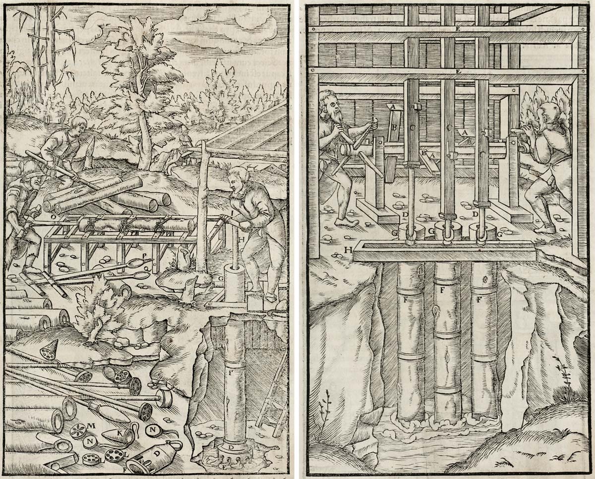
An extraordinary set of woodcuts published in Georgius Agricola’s 1556 treatise De Re Metallica (On the Nature of Metals) show a series of lift pumps of increasing complexity, some powered by hand, others by water wheels, all used to drain mines. In one (shown in the image to the left at the top of this post), a laborer operates a wooden pump while another cores logs for pump boxes and pipes. Scattered in the foreground are spears, pistons, grates, and all the other parts needed to build the pump.

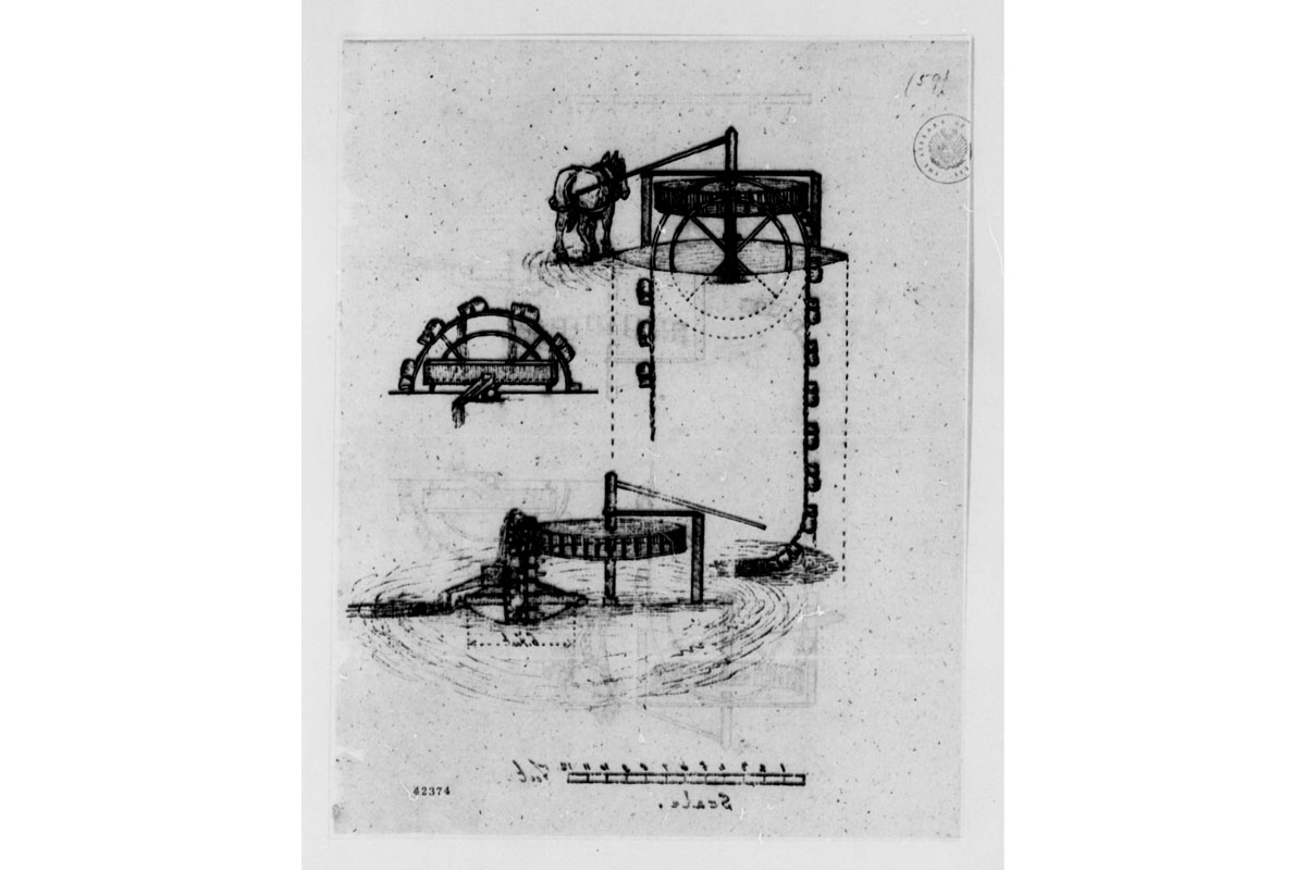
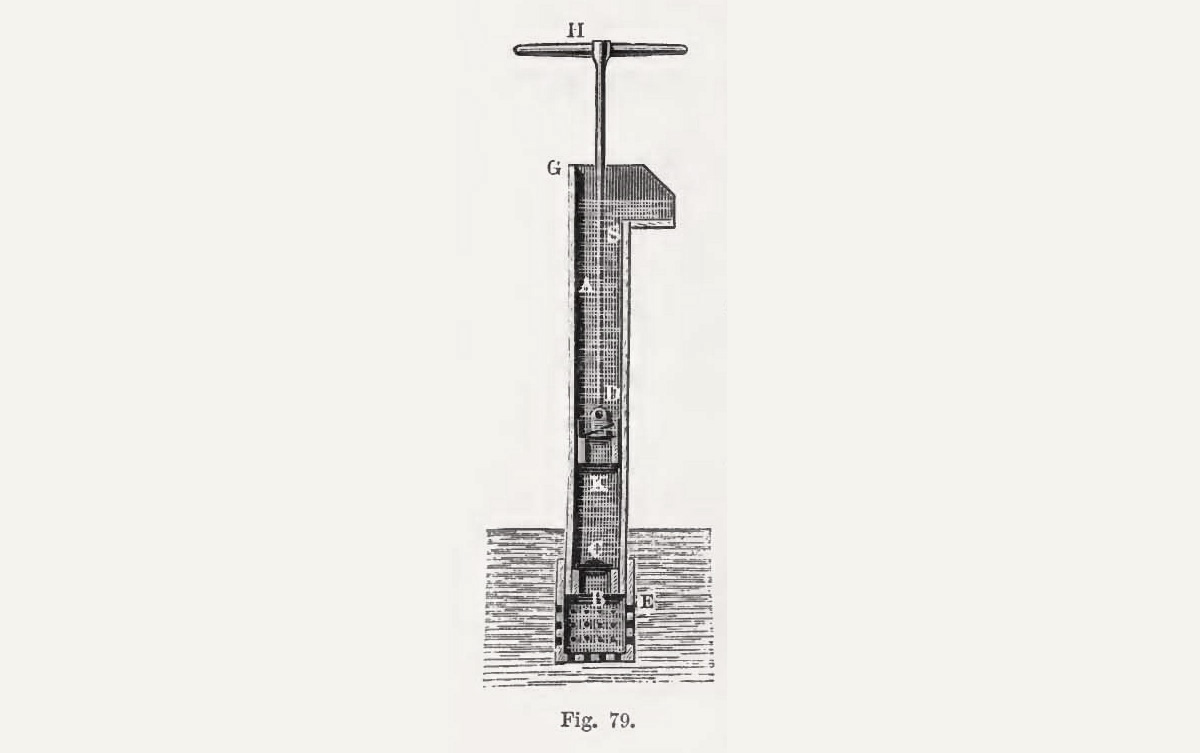
Agricola’s pumps are functionally equivalent to the simple machine shown in the second image, above. That diagram was published in 1897, more than three centuries later. The hand-operated pump it depicts was used to drain excavations. Not much had changed.

A Digest of Patents 1790-1839
From 1790 through 1838 more than 100 patents were awarded for various types of pumps. Sadly, the records for almost all of them were lost in an 1836 fire. (“Digest of Patents of the United States, from 1790 to January 1, 1839,” Library of Congress via HathiTrust Digital Library)

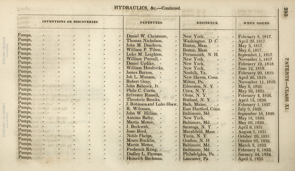
It wasn’t for want of trying. More than a hundred patents for pumps were granted during the early 19th century. Some were featured in technical publications such as The Franklin Journal and American Mechanic’s Magazine, which may have summarized their collective significance in this review, published in 1836: “there is not in the description any thing that regards construction or arrangement which is worthy of particular notice, or that is in any respect superior to the pumps now in use.”

The diggers excavating the Erie Canal would have to solve the vexing problem of excess water by using simple machines built as they had been built for centuries — from wood, wrought iron, and leather.

The virtue of simplicity

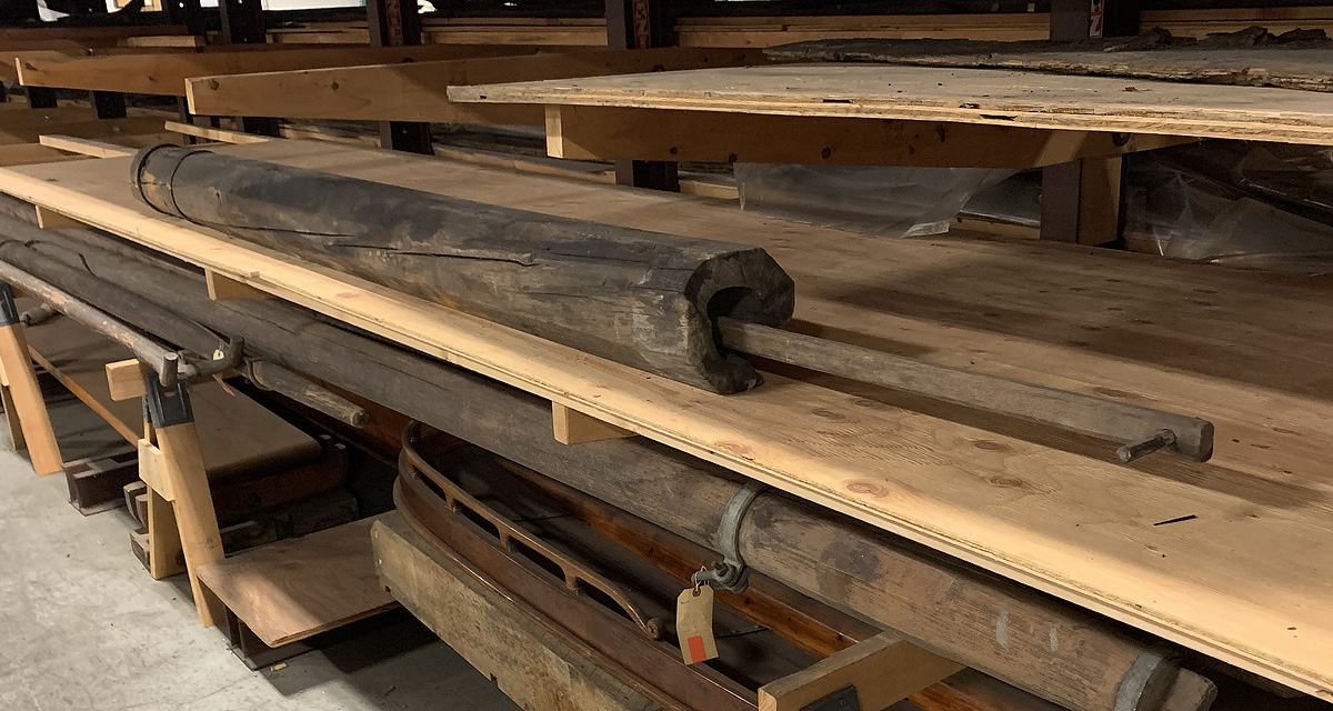
There is little doubt that most of the pumps used along the Erie Canal were made of wood. The raw material was readily available, and there is good evidence that the machines were made and repaired by local craftsmen.

As Thomas Ewbank wrote in his 1849 opus, A Descriptive and Historical Account of Hydraulic and Other Machines for Raising Water, Ancient and Modern: “The facility with which wooden pumps are made and repaired, the cheapness of their material, the little amount of friction from pistons working within them, and their general durability, have always rendered them more popular than others.”

Ewbank, an English immigrant who briefly served as commissioner of the U.S. Patent Office, also described a simple piston used by pump builders in upstate New York. It was a “hollow cone or truncated cone of strong leather, the base being equal in diameter to that of the pump chamber or cylinder . . . When thrust down it collapses and permits the water to pass between it and the sides of the chamber, and when its motion is reversed, the weight of the liquid column above it, presses it out again.”

Picture an inverted parasol that closes and opens as the pump handle is lowered and raised.

The design, Ewbank wrote, “has long been known in some parts of the United States. We noticed it twenty years ago [that is, during the late 1820s] at New Rochelle, Westchester County, in [New York] and were informed by a pump maker here that they ‘always had it.’ It is not however universally known, for in 1831 a patent was taken out for it.”

That patent was awarded to Noble Phelps, of Turin, New York, on October 20, 1831. A review published in the Journal of the Franklin Institute noted that the improvement was a piston or “leather bucket in the form of the letter V . . .”

A Treatise of Mechanics
The fourth edition of “A Treatise of Mechanics,” by Olinthus Gregory, published in London in 1826, includes descriptions of these two simple pumps, which could have been built by local craftsmen on the New York frontier. (University of Michigan via HathiTrust Digital Library)

Other accounts emphasized the advantages of simple machines made from everyday materials.

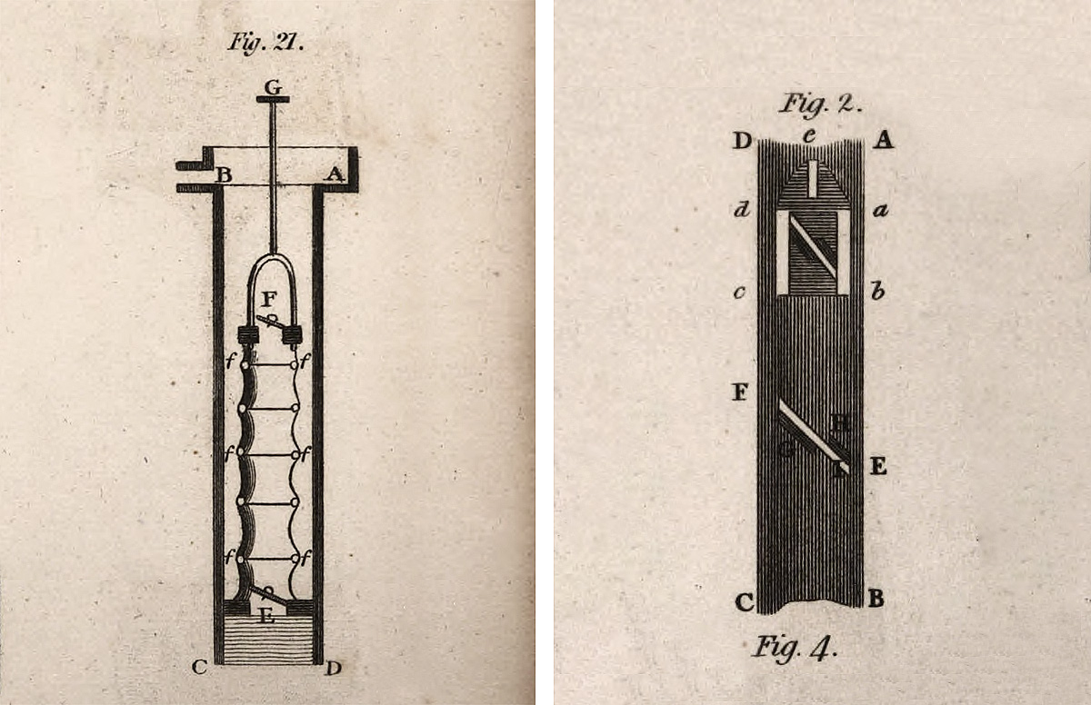
In 1815 Englishman Olinthus Gregory in A Treatise of Mechanics — Theoretical, Practical, and Descriptive described a pump that could be built by “a common carpenter.” The design (above, at left) used a cylindrical bellows made of leather or canvas instead of a piston. The main advantage was that a precise fit between the bellows and pump box was not required, so the box could be cylindrical or square. The lack of friction reduced wear and (in theory, at least) extended the useful life of the machine.

Gregory also described simple butterfly valves (above, right), fabricated from wood and leather, that would fit inside a square pump box.

Elsewhere, he goes into some detail how wood pistons should be lined with leather to create watertight seals with minimal friction — a passage that sheds some light on items found in Erie Canal contractor receipts (such as this one from January 13, 1819: “for Leather to Leather the Boxes for two pumps”).

London Society for the Arts
Jacob Perkins’ award-winning pump borrowed several details, including a square box built of planks and V-shaped valves attached to the piston and intake, from earlier designs. (University of California Libraries via HathiTrust Digital Library)

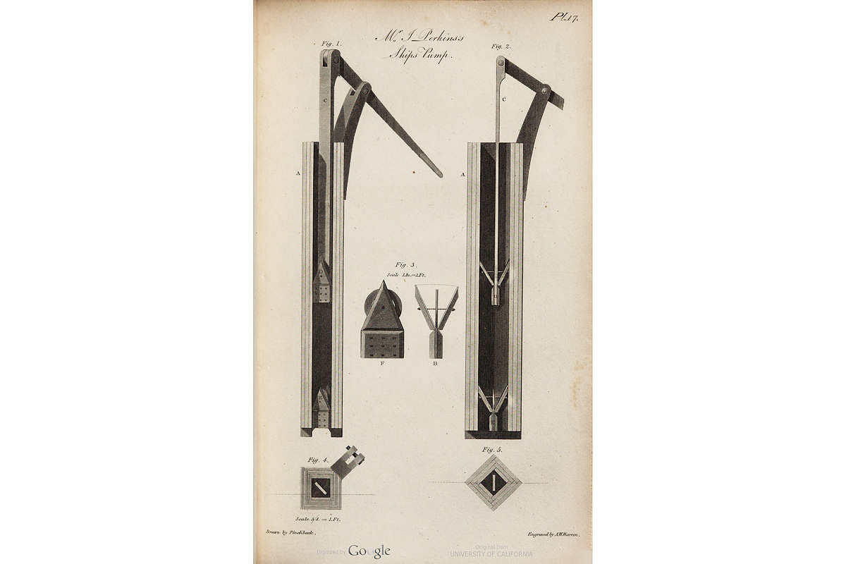
The London Society for the Encouragement of Arts, Manufactures, and Commerce in 1820 awarded a “large gold medal” to Jacob Perkins for devising a ship’s pump built of planks. “The object of the peculiar modification of this pump,” notes the Society’s Transactions, “is that of enabling sea-faring people to construct a pump while at sea from materials always to be found on board; viz. deal boards or planks, leather, nails, canvas, and tar.”

The plank construction eliminated the “necessity of boring the barrel, as in the usual pumps.”

New York State Archives
The body of this simple pump is made from a single, cored log. It likely served as a bilge pump on a 19th-century Erie Canal boat. (New York State Museum)

Cored logs, of course, had been used as pumps since ancient times, as shown in Agricola’s woodcut. They also were used as water pipes, and references to them can be found in Erie Canal contractor receipts. (For example, in 1823 John M. Smith was paid $50.79 for, among other things, “5 Rods of new pump logs laid under Canal.”)

Two are better than one

Over the centuries, builders experimented with various combinations of pumps. Several woodcuts in Agricola’s book show machines made up of two, three or even more pump boxes, arranged side-by-side (see the first image at right, above) or one above the other, like a staircase.

The simplest arrangement combined two pumps with a single lever operated by two men. Bilge pumps on the 74-gun battleship U.S.S. North Carolina, launched in 1820, worked this way, according to Ewbank: “The levers are double, and shaped like those of fire-engines, staves of wood being slipped through the rings whenever the pumps are worked.”

American Mechanics Magazine
In a letter to the editor of “American Mechanics Magazine,” published in May, 1825, a reader provided a description and this sketch of a double lift pump. (Harvard University via HathiTrust Digital Library)

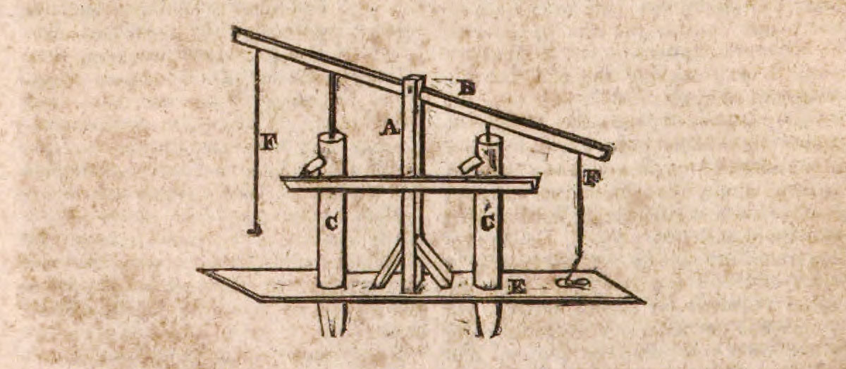
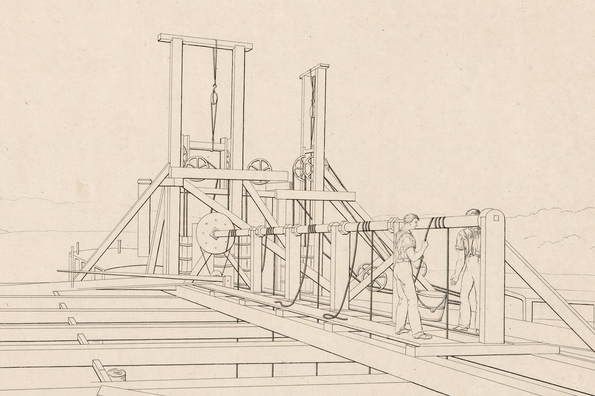
In a letter to American Mechanic’s Magazine, May 21, 1825, a P. Vanryde mentions a double pump that he had “frequently seen working in Holland.” He helpfully included a sketch: “Thus two men can raise an immense quantity of water in a day, as there is a constant stream from one or the other.” The scale of Vanryde’s drawing is not shown, but similar illustrations indicate that the pump barrels were taller than man-height. The lever is operated by pulling on the ropes at either end.

(This may be a good place to insert a reminder that the first European settlers of the Hudson and lower Mohawk valleys were the Dutch, masters of hydraulic engineering who would have brought this technology with them.)

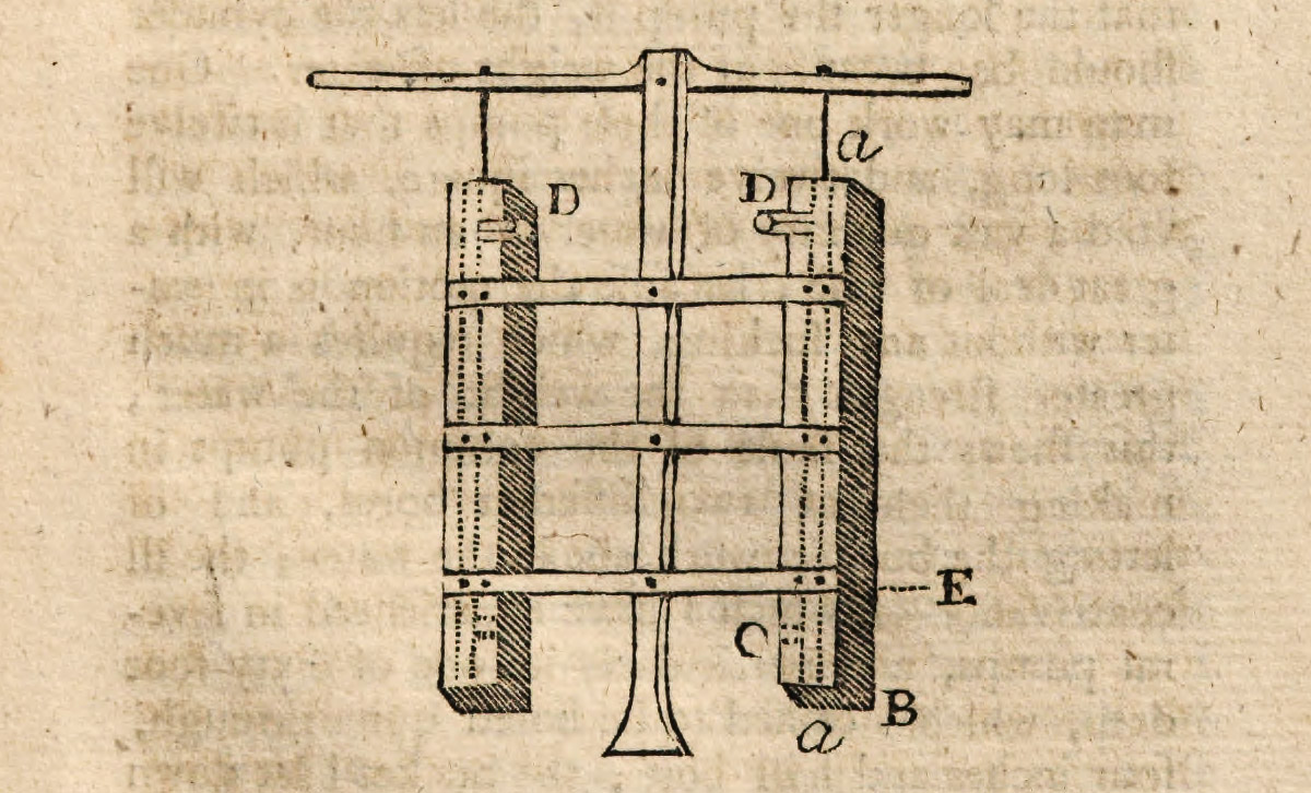
One of the most intriguing examples dates from more than 60 years earlier. In Whole Art of Husbandry; Or, the Way of Managing and Improving of Land, published in 1761, Englishman John Mortimer teaches readers how to mine marl deposits (marl, a mixture of clay and calcium carbonate, was widely used as a soil conditioner) and what to do when the pit became flooded with spring water.

“I shall propose one of the cheapest and best pumps that is for their use; which is to take four deals or other boards, which joint and nail together; and if some plates of iron be nailed over the edges of them, it will strengthen them much; these pumps may be made single, with a common pump-handle to them for one man to work them, or double for two men, as in the figure . . . One man may work one of these pumps that is twelve foot long, and twelve inches square, which will void a vast quantity of water in an hour, with a great deal of ease.”

Whole Art of Husbandry
This two-cylinder pump operated by two men was described in 1761 by John Mortimer in “The Whole Art of Husbandry; Or, the Way of Managing and Improving of Land.” He proposed using this “cheapest and best” pump to drain marl pits. (Harvard University via HathiTrust Digital Library)

Later authors copied Mortimer’s design, which may be evidence of its popularity — and also evidence that it worked.

Could this, or something similar, have been used on the Erie Canal?

The marl reference is an interesting coincidence. The crumbly, stony material was encountered by contractors in several locations along the canal line, where it was notoriously difficult to excavate.

But Mortimer’s pump also satisfies all the requirements for the kind of machine we’d expect to find on the New York frontier from 1817 through 1825: The simple plank design could have been built by any local carpenter or millwright, the finished pump could have been operated by one or two men, and (most important) it could “void a vast quantity of water . . . with ease.”

Something tells me we’re getting close.


If you or someone you know is familiar with 1820s construction technology, I’d appreciate hearing from you. Please leave a comment here or contact me via email at smb (at) steveboerner (dot) com. Thanks!

The mystery of the missing pumps, part one

Potomac Aqueduct
Large steam-powered pumps were used to drain cofferdams during the construction of the Potomac Aqueduct near Washington, D.C. in the 1830s. (Library of Congress)

Work on the Cayuga Marsh scene had been going really well. The basic terrain was in place and ready for the next step – adding models of the workers and the machines they would have used.

But a brief passage in a primary source suddenly brought everything to a halt. It occurs in an 1824 legislative committee report on a financial scandal that was ending the career of Myron Holley, treasurer of the canal commission.

Alfred Hovey and Abel Wethy, the contractors responsible for the Cayuga Marsh canal section and the Rochester aqueduct, appeared to have been overcompensated by Holley for their work. Suspecting collusion, the committee scrutinized their accounts and visited both locations. The contractors were cleared of wrongdoing, but in its report the committee documented the difficulties they had encountered while constructing the canal through the marsh, where the excavation was often under water.

The report reads: “The great difficulties which had to be encountered in the prosecution of this work, was a subject of deep anxiety to the [canal] commissioners, as this section was a connecting link between finished portions of the canal on each side of it. . . . Hovey & Wethey went on with the work in the winter of 1822, and prosecuted it with great energy. In the prosecution of this work, both summer and winter, the contractors were compelled to keep pumps in operation, night and day, to enable them to go on with the work.”

That last sentence was the show stopper. I had no idea what kind of machines they were talking about.

The handful of other pump references in the canal commissioners’ reports are not helpful. Nowhere do they offer even the briefest description. Why should they? This was pedestrian technology. At the time, everyone knew what an early 19th-century excavation pump looked like and how it worked.

Until we didn’t. As with many other details of early Erie Canal history – especially those concerning the daily lives of working people – much of what we once knew about these poorly documented machines has, apparently, been lost.

What did the machines look like? What were they made of? How were they powered? By hand? Horse? Steam?

It’s an historical puzzle, and until it’s solved the Cayuga scene will have to be put on the shelf. That’s okay – there are plenty of other projects to work on.

Beyond that immediate concern, though, is something larger. The better we understand the technology of the day and the tools that were used, the more we will understand the day-to-day experience of the workers who built the canal.

Adams Basin
Portable steam engines, which powered a variety of tools and machines, were a ubiquitous feature at construction sites along the Barge Canal enlargement in the early 20th century. (Ogden Historical Society)

Could the pumps have been steam-powered?

Let’s deal with this question right away.

The steam engine was undergoing rapid development in the early 19th century. The patent on James Watts’ steam engine expired in 1800, allowing competitors to borrow and improve upon his design. In the United States, Robert Fulton built the first commercially successful steamboat and began regular passenger service on the Hudson River in 1807. The Stourbridge Lion, imported from England, would become the first railroad locomotive in the United States in 1829.

In Triumph at the Falls: The Louisville and Portland Canal (U.S. Army Corps of Engineers, 2007), authors Leland R. Johnson and Charles E. Parrish place the first use of steam power for canal construction in late 1827, when contractors on Kentucky’s Louisville and Portland Canal installed a steam pump to drain lock pit excavations.

A few years later, immense steam engines would drive pumps and machinery for construction of the Potomac Aqueduct in Washington, D.C.

But of course, that all came later. For the workers stuck in the middle of a marsh on the New York frontier in 1822, steam-powered pumps would remain at best a distant dream.

Following the money

Excess water bedeviled contractors and workers not only at Cayuga, but all along the canal line. Pumps – making and repairing them, using and transporting them – are frequently mentioned in receipts issued to contractors and subcontractors.

Engineer Marshall Lewis, who perhaps brought more practical experience to the field than any of his peers, having previously designed and built locks in Waterloo for the Seneca Lock Navigation Company, also built locks and aqueduct foundations for the Erie Canal. Perhaps because of the nature of this work, Lewis spent a lot of money on pumps.

Receipt to George M. Stowits
Receipt made out to George M. Stowits of Currytown, Montgomery County, on July 19, 1827 for the amount of $4 for “making and repairing pump boxes.” (New York State Archives)

For example one of his receipts, from December 1818, records a payment of $12.63 to Alvin Upham of Elbridge “for two Large pumps.” ($12.63 in 1818 would be roughly equivalent to $216 today.) Another, to Nathan Young of Jordan dated January 1819, lists an expense of $2 “for two hands to pump one Night.”

Removing unwanted water from excavations was always labor intensive, and the expense could be considerable.

The worst example might be the lower end of the Deep Cut near its junction with Tonawanda Creek, where work was constantly hampered by flooding. “Pumps, worked by horse power, were introduced on almost every section,” reported the canal commissioners in 1825.

This is confirmed by a December 1825 receipt from Principal Engineer Nathan Roberts to contractors Lane and Snyder that included “the expense of several horse pumps and of 163 days pumping estimated at $15 per day,” which would have come to $2,445, or about $56,715 today.

Earlier that year, in August, Francis B. Lane of Lane and Snyder would provide a receipt to Peter Cater for the amount of $3 for “2 days work at hawling [sic] pump Frame out of the canal.” This may have been a frame for one of the horse pumps, which (I’m guessing) would have been large, semipermanent chain-and-bucket installations.

I can find no other references to horse pumps in the commissioners’ reports or other state documents. But chances are they were used elsewhere when the expense was justified.

Horse Pump
An undated drawing of a chain and bucket pump powered by a horse whim. (The Thomas Jefferson Papers at the Library of Congress)

More interesting are the receipts that provide details on pump construction and repair.

Of particular interest is one issued by Lewis in January 1820 to Jedediah Richards for various items and services, including making patterns for culvert frames, a hammer pattern, three “pile Machienes,” making two pumps “at $7.00 per each,” and “for use of my pit saw.” Richards obviously worked with wood and may have been a sawmill operator – not an unusual occupation for frontier entrepreneurs. This strongly implies that the pumps were made of wood, perhaps from planks produced by his saw.

Richards is also a good example of a familiar early 19th-century archetype – the intrepid Yankee inventor. Between 1828 and 1832 he was awarded three patents: for a machine to punch iron and steel, a machine to manufacture window sashes, and for designs for an elevated railway and the “cars used thereon.” (An earlier 1810 patent, for a machine to manufacture excelsior, or wood wool, is credited to a Jedediah Richards 3rd, of Norfolk, Conn. – perhaps the same person.)

Further evidence that at least some of the pumps were made of wood is provided by a May 1827 receipt from contractor David Fitzgerald to Matthias Langdon for “making two box pumps.” Langdon would later be described by Jeptha Root Simmons in Frontiersmen of New York (Albany, 1882) as the “boss carpenter” of a crew that built a bridge in Fort Plain in 1828.

Blacksmiths provided many parts for pumps and repaired them, too.

A receipt from December 1818 from Lewis to James W. Redfield includes, among other items, “4 straps pumps . . . fix band for pump . . . 1 strap pump . . . 2 small bands for pump.” Local Onondaga County histories identify Redfield as one of the area’s early blacksmiths. What are “straps” and “bands”? I have some ideas which we’ll get into later.

An August 1823 receipt from contractor Caleb Hamill, who built a series of locks along the eastern end of the canal (and who figures prominently in Walter D. Edmond’s fictional narrative Erie Water), to blacksmith Nicholas F. Lighthall includes expenses for framing a pump box, “3 eye bolts for pump brakes,” and “repairing pump spears.”

In a piston pump, which is clearly being described here, the pump box is the chamber in which the piston works; a brake is the pump handle, and a spear is the rod that connects the handle to the piston.

A January 1819 receipt from Lewis to Casey McKay of Jordan includes “Leather to Leather the Boxes for two pumps” – perhaps the same pumps purchased earlier from Alvin Upham. About two weeks later another to Thomas Moseley mentions “Leathering pump boxes for the use of the Erie Canal at Jordan aqueduct.” Many other receipts refer to leather work.

Finally, an example that brings us full circle: a May 1825 receipt to Richardson and Beals for “items of extra work done by them in their subcontract on the Erie Canal through the Cayuga Marshes.” The items include “excavating pump pits below bottom in order to prepare for pumping.”

Summing up

A few things seem to be coming into focus.

First, several kinds of water pumps of various shapes and sizes were likely used along the canal. Many seem to have been fabricated by local craftsmen along the line.

Second, aside from the large horse pumps on the Mountain Ridge and a single reference elsewhere to “screw pumps,” most appear to have been hand-powered piston lift pumps.

Third, some if not most pump boxes were made of wood, and fittings and moving parts were forged from iron. Pump boxes may have been lined with leather to provide a watertight seal, and pistons may have been made of leather.

Fourth, where it was important to completely drain the excavation, pump pits would be dug into the bed of the canal prism. Perhaps the pits were lined with stone or timber to reduce the amount of mud and debris that might clog the pump.

Finally, judging from the quantity of receipts for repair work, these machines regularly broke down and had to be fixed, maybe by the same hands that built them in the first place.

So what did they look like? We’ll explore that in part two.


A final note for those who stayed with me to the end. If you or someone you know is familiar with 1820s construction technology, I’d appreciate hearing from you. Leave a comment here, or contact me via email at smb (at) steveboerner (dot) com.