The 1912 Torpedo Runabout chassis was identical to those used for all models produced that year.
With just a few minor modifications, the 1911 chassis is converted into a 1912 chassis. With its raised steering column, shorter hood, and square-cornered dashboard, this chassis was used for all T models produced that year. Ford was standardizing its designs to simplify production.
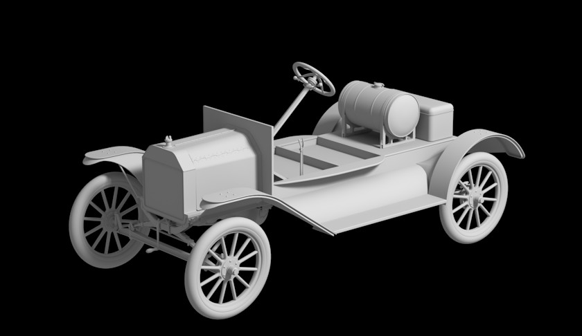
Chassis with deck, splash aprons, and fenders. The gas tank and toolbox are mounted on the deck.
The passenger compartment floor, rear deck, splash aprons, and fenders are next. The front fenders look straightforward but are surprisingly complex three-dimensional shapes. It would take me three or four attempts before I could finally get them right.
The Torpedo was unusual in that the gas tank was mounted on the rear deck behind the passenger compartment. In most T models, it was mounted beneath the seat.
It’s beginning to look like an automobile.
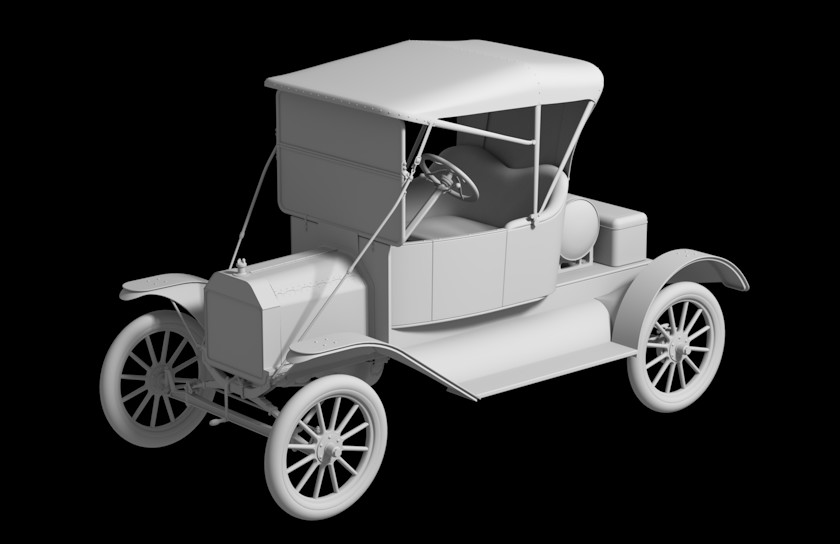
The top is attached to the windshield with a leather strap.
The passenger compartment, windshield, and top are added to complete the body. The windshield and imitation-leather top could be folded down to convert the Runabout into an open-body car. Since it will be used in a scene set in mid-October, I figured both should be left in place.
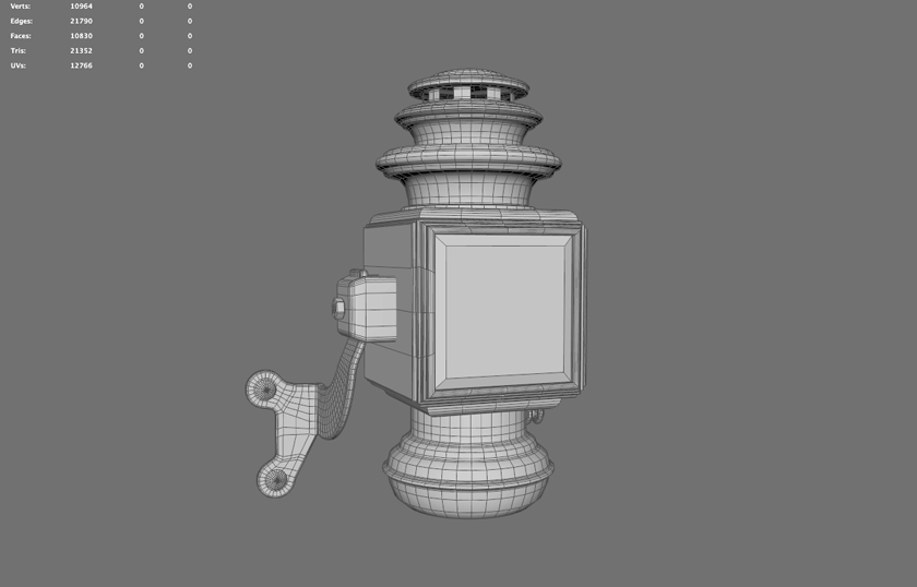
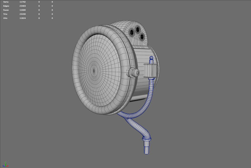
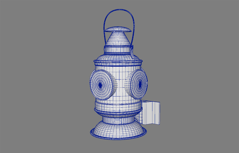
Ford used third-party suppliers for many Model T components. This Model 204 kerosene side lamp was manufactured by the Atwood-Castle Company.
Now for the brass fixtures. Headlamps, side and rear lamps, bulb horn and other parts were manufactured by third-party suppliers and often similar to those used on horse-drawn carriages. At the Ford plant they were simply bolted on to the T frame or body.
The side and rear lamps used kerosene and would have to be lit by hand before an evening drive.
The Jno Brown 19 headlamp was powered by acetylene gas.
In 1912 the T’s electrical system was limited to the magneto (powered by a handcrank) used to start the engine. Headlamps were powered by acetylene gas created in a cylindrical carbide generator mounted on the driver’s side running board.
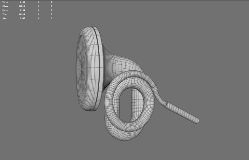
Rubes double-twist bulb horn.
And of course the familiar Model T horn was powered by a bulb mounted on the driver’s side of the passenger compartment.
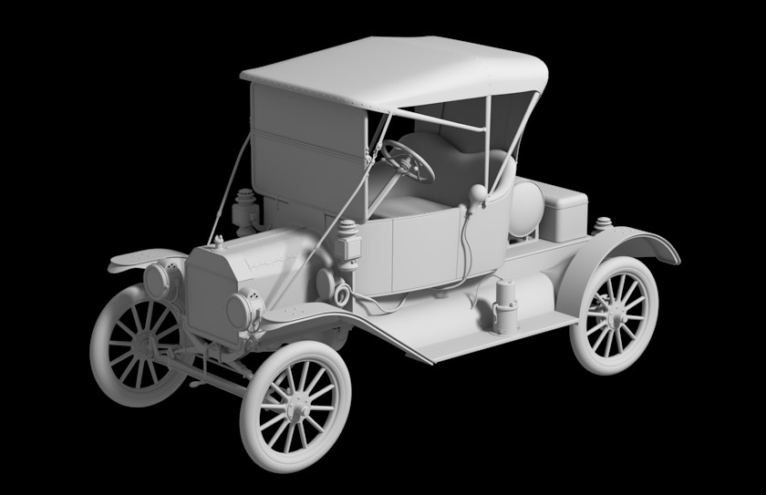
Completed Torpedo Runabout model.
Once the brass components are all in place the model is complete and ready for shading.
The Model T Torpedo Runabout, as pictured in the April 1912 Ford Motor Co. catalog.
Summer has been busy and opportunities to work on the Adams Basin scene somewhat scarce. So far all available time has been spent developing a set of good quality human figures. The base models are done and mostly rigged and I’m now fine-tuning the skin weights. As that work slowly progresses I’ve decided to take a break to do something a little more quick and fun.
The scene seems to have an emphasis on transportation so the obvious thing to add is a motorized vehicle – a Ford Model T.
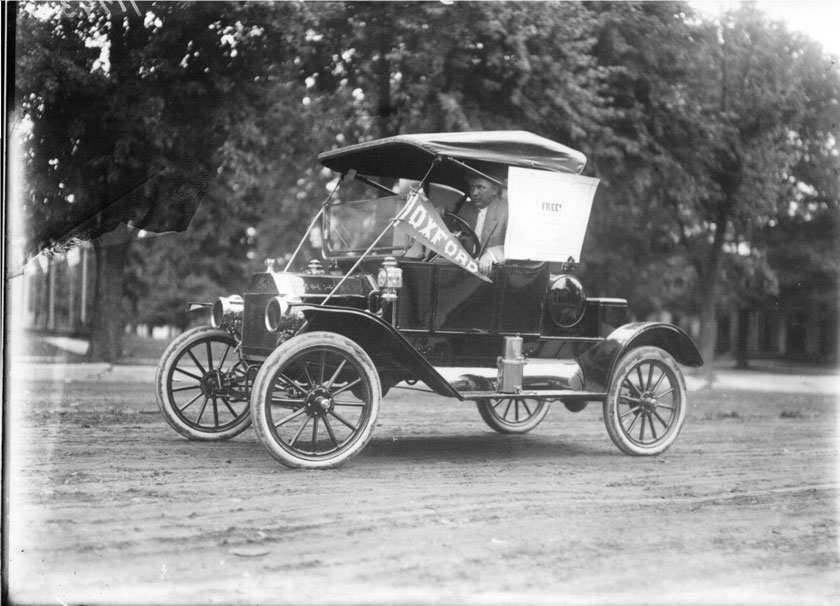
A man drives a 1912 Ford Torpedo Runabout during July Fourth festivities in Oxford, Ohio (Miami University Libraries Digital Collections).
And not just any old Model T. Since this is my scene I’ve decided to add a particularly interesting version of the T – the 1912 Ford Torpedo Runabout.
The Model T, of course, was the electric interurban railroad’s nemesis. Introduced at about the same time – 1909 – Henry Ford’s “universal car” was initially dismissed as an expensive novelty that would never compete with the railroads, steam or electric. But no one anticipated Ford’s genius for mass production and marketing. The price of the T quickly dropped year over year as the numbers produced grew. And soon it became the answer to the problem that the interurban had struggled to solve – providing simple, reliable transportation for the country’s rural population.
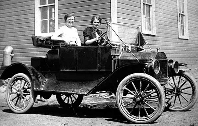
Two teachers in a 1912 Ford Torpedo outside Lamson High School in Dassel, Minnesota. Many period Model T photos show women behind the wheel – not surprising given the unprecedented mobility and independence that the car gave them, especially in rural areas (Model T Ford Fix).
The 1912 Ford Torpedo Runabout was introduced in October, 1911. The new model eliminated some of the racier aspects of the 1911 Torpedo, which had a longer hood and lower seat, perhaps to make it easier to manufacture. As far as I know the 1912 model year is the only year that this particular car was produced. The cost was $590, a not insignificant sum in those days, equivalent to about $16,000 today. It was one of two model Runabouts produced for 1912, and between them 13,376 were manufactured that year out of a total of 68,773 for all T models.
Altogether around 15 million Model T Fords were produced from 1909 through 1926, and out of those perhaps a half million survive today. Out of those, it is said that around 200,000 to 300,000 are still drivable.
Which explains the large and enthusiastic T community and its equally large and enthusiastic online presence. There’s lots of great information about the T on the web.
The reference drawings I’m using are period Ford blueprints now held on microfiche at the Benson Ford Research Center at The Henry Ford in Dearborn, Michigan. Other information has been gleaned from Model T Ford Fix (the most impressive blog on any subject that I’ve ever run across) and the Model T Ford Club of America’s extensive online Encyclopedia. The folks at MTFCA have been helpful as well. Plus many other online sources too numerous to list here.
We’ll be building our 1912 Torpedo out of parts from various years, based on the availability of blueprints and other references. The same frame was used for Model T cars from 1910 to 1913.
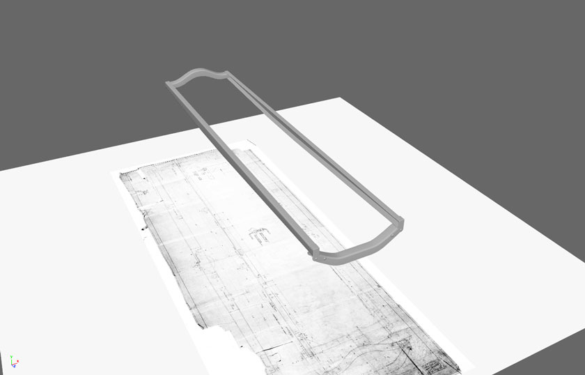
All 1912 Ford Model T automobiles were built around the same chassis, which was itself based on a simple steel frame long enough to accommodate the car’s 100-inch wheelbase.
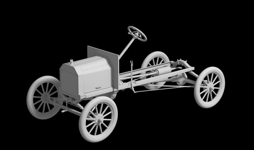
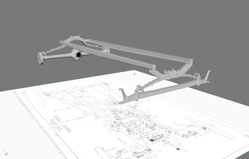
Front and back axles and springs are based on blueprints of the 1911 Torpedo chassis.
Leaf springs attach the frame to the front and back axles and provide the basis for the T’s legendary, rugged suspension.
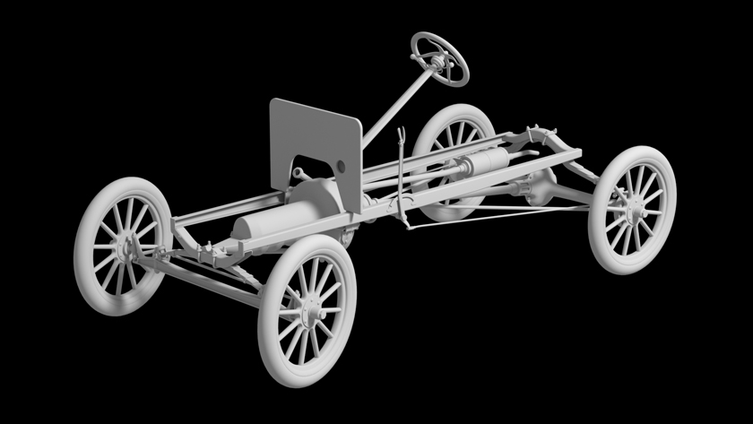
Rendering of the 1911 Ford Torpedo chassis. Most of the details under the hood, including the top of the motor, will not be finished because they will not be visible when the model is completed.
After adding wheels, dashboard, steering and brake gear, the 1911 chassis is nearly complete. There are two options now since I have body plans for both the 1911 and 1912 Torpedo models. The chassis will need a few minor modifications for 1912 but otherwise is good to go either way. The drawings for the 1912 Torpedo are more complete – and its purchase date nearer to the 1916 date of the scene – so I’ll probably go with it.
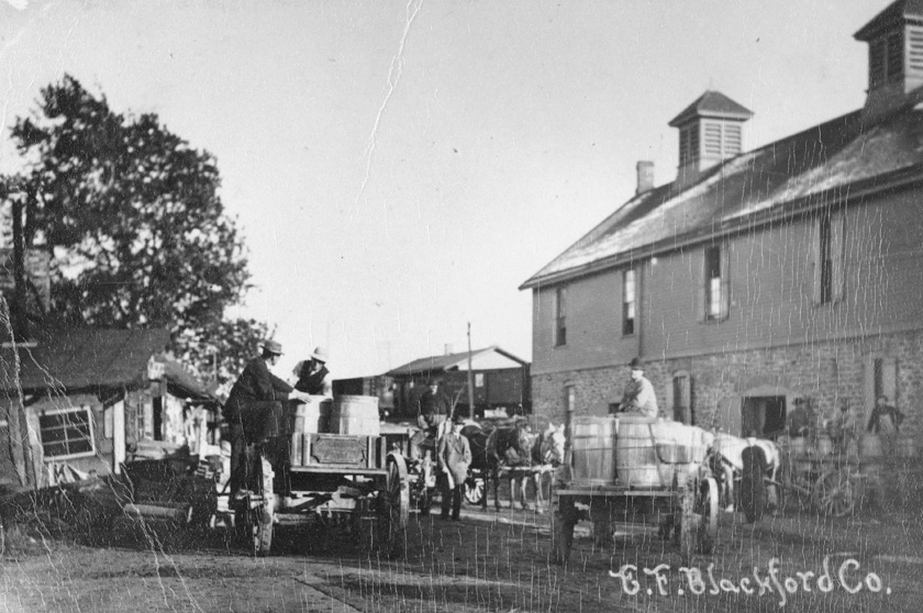
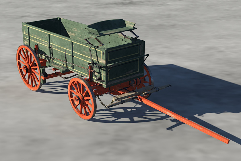
Farmers bring their produce to E. F. Blackford Co., a fruit wholesaler in Adams Basin. The photo was taken sometime before August 1909, when the large warehouse at right burned down. Wagons shown are a box farm wagon (left) and a heavy duty truck or dray (right). (Ogden Historical Society)
The Adams Basin scene is shaping up bit by bit, much of it unplanned. But if there is a theme, it might be “transportation.”
The juxtaposition of the Erie Canal, lift bridge, steam-powered and towed canal boats, and an interurban passenger car isn’t accidental. The original canal followed a natural corridor, and once the route was pioneered other modes of transportation soon followed.
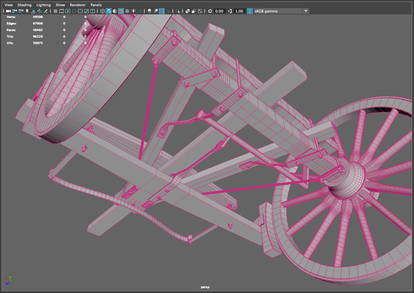
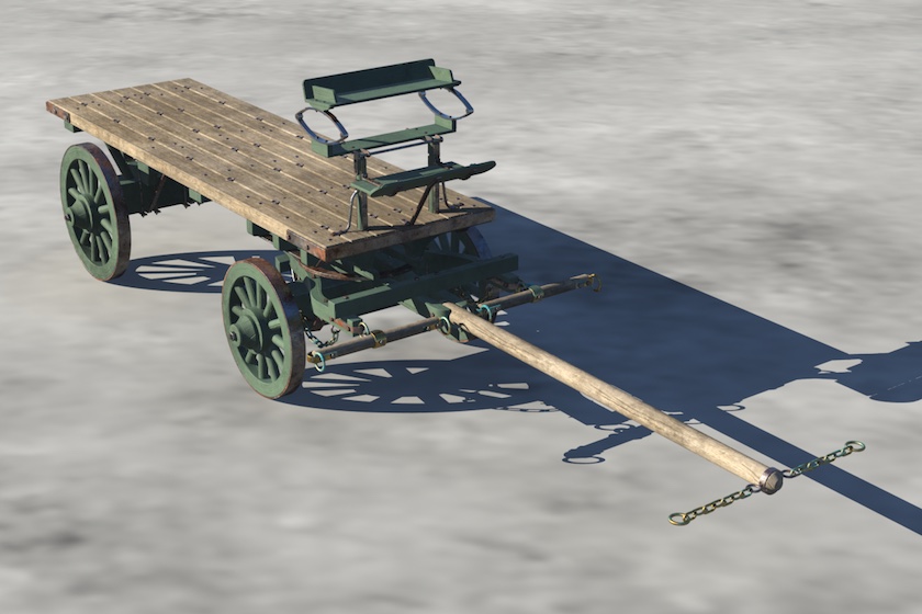
The front and rear running gears of the Studebaker farm wagon take shape.
Thousands of businesses also sprung up along the canal. In Adams Basin one of these was the E. F. Blackford Co., a fruit wholesaler that built a complex of warehouses and a railroad siding that allowed it to ship its produce on the New York Central Railroad, which paralleled the canal. (All of these structures, including the railroad, have long since disappeared.)
The warehouses are too far from the bridge to be included in the scene, but in a nod to the business, we’ll include a farm wagon on its way to deliver a load of produce.
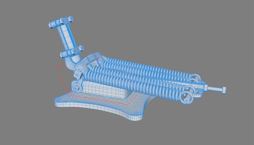
View from beneath shows the completed brake assembly built into the rear running gear.
Back in the day, the ubiquitous box farm wagon was manufactured by various suppliers, and nearly all followed the same basic pattern. We’ll base ours on the wagon built by the Studebaker Brothers Manufacturing Company in South Bend, Indiana. (Later it became the Studebaker Corporation and manufactured automobiles until the early 1960s.)
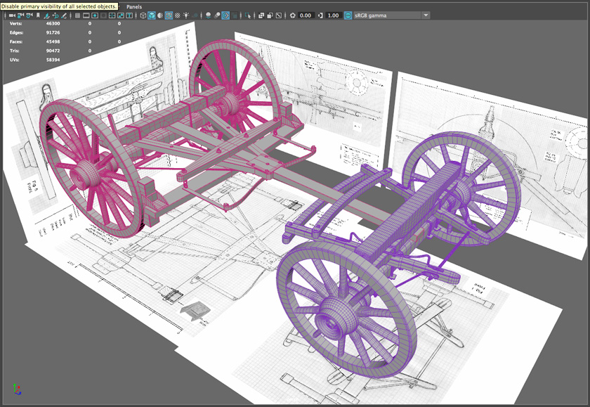
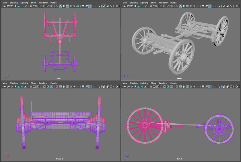
As a reference I’m using a fine set of plans of a Studebaker Wagon drawn by Bob Kuntz. The plans diagram the wagon’s running gear or wheel assemblies. The box and seat are based on historical photos.
Orthogonal and perspective views of the running gear. The front view (lower left) clearly shows the 3-degree camber (outward tilt) of the wheels.
The wagon, lightweight and rugged, featured dished wheels (to increase strength) that were cambered (tilted out to keep the bottom rung perpendicular to the ground). The rudimentary brake system was optional. Most wagons were shipped without brakes, and drivers counted on their skill and the ability of their teams to control the vehicle on grades.
It’s interesting how the lives of rural Americans had barely changed despite a century of innovation. Even as canals and railroads were built, steam harnessed to power boats and locomotives, and electricity generated to lift steel bridges and push interurban cars, the average farmer still depended on horse power and centuries-old technology to get his produce to market.
The wagon model shaded in Terragen and ready for placement in the scene.
Besides the farm wagon I’ve also built a dray, a heavy-duty truck based on model plans from the Vilas County Lumber Company.
The horse-drawn dray was the heavy-duty pickup truck of its day.
Now we just need horse teams, drivers, and produce for the wagons to haul.
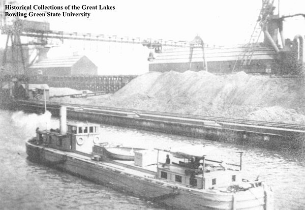
Undated photo of the steam canal boat Ashford. Piles of salt in the background indicate it may have been taken in the Syracuse area (Historical Collections of the Great Lakes/Bowling Green State University).
The end of the animal-powered canal boat, after decades of encroachment by steam vessels, came quickly.
Primitive steamboats had been sighted on the canal since the 1840s but would remain a novelty for most of the century. Canal enlargement in the mid-19th century and improved steamer designs gradually changed things, though, and around 1880 the first practical steamers were introduced. The advantage of steam power was immediately apparent. While animal-powered fleets were limited to two vessels – so-called doubleheaders – a single steamer could push one boat (a consort) and tow up to five or six more.
The final Barge Canal enlargement of 1908–1918 permanently settled things. As each new section came online the towpath itself began to disappear. When the enlargement was completed, only powered boats could navigate the entire distance between Buffalo and Albany.
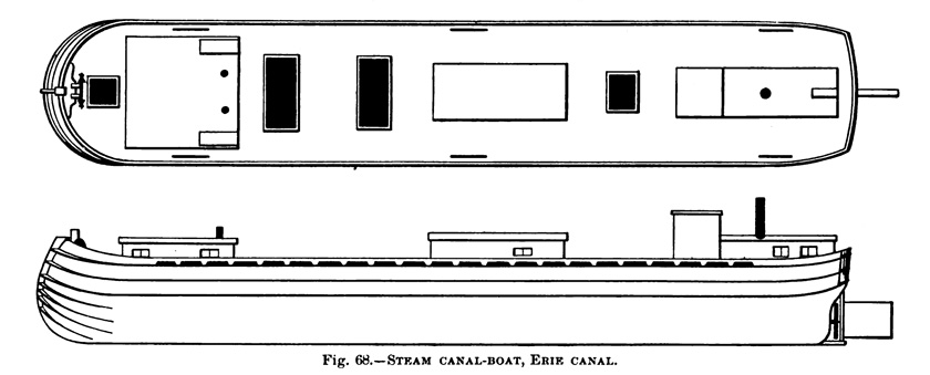
In 1916, the date of my scene, most steam-powered boats on the canal were of two types, both built of wood: tugboats and steam canal boats. The U.S. government’s 1884 Report on the Ship-Building Industry of the United States helpfully includes a diagram of a steam canal boat, a functional design (besides pushing and towing unpowered boats, it could carry its own full cargo) that remained in service well into the 20th century.
Diagram from the 1884 Report on the Ship-Building Industry of the United States illustrates a typical wooden steamer built on a laker hull.
This was the design I wanted for my 3D model – new technology (steam power) grafted onto traditional design (the wooden laker hull). Now I just needed to find a specific vessel on which to base the model.
Unfortunately, period photographs of Erie Canal steamers are about as rare as hen’s teeth. Repeated online searches turned up nothing.
Eventually I learned to combine two sources: the List of Merchant Vessels of the United States, published annually by the Department of Commerce, and the Great Lakes Vessels Online Index, maintained by Bowling Green State University. The 1916 edition of the List included around 40 vessels designated as “Scb,” or steam canal boat. Searching for each of these on the Bowling Green site resulted in a handful of matches – some of which included photographs.
For various reasons, including the clarity of the photo and strong evidence that the boat operated in this area, I chose a steamer named the Ashford. It is pictured at the top of this post.
According to the Index, the Ashford was 95 feet long and 17 feet 8 inches wide. It was built in 1883 in Buffalo and sank in the Barge Canal near Schenectady in November 1919 – “a total loss.”
Filling in the blanks
Online searches turned up several references to the Ashford. The earliest was a notice from the Buffalo Express reprinted in the August 22, 1883 issue of The Coal Trade Journal, which identified the Ashford as one of three canal steamers constructed by the Rochester and Pittsburgh Railroad Company.
The Rochester and Pittsburgh Railroad Company was founded in 1881 to haul coal from western Pennsylvania to Rochester and Buffalo. That was as far as its lines extended. The canal boats were to be used to ship the coal to the lucrative New York City market. The company’s 1883 annual report explains that land purchased in Buffalo will be developed into a railyard, but also that
. . . We have made two slips to accommodate eight canal boats . . . and have constructed coal shutes [sic] . . . so that coal can be shipped in canal boats at minimum cost.
The assumption that the Erie Canal was always in competition with the railroads, then, is an oversimplification. Things were more complicated, especially early on when hundreds of railways were being formed and struggling to grow and survive. In this case the R&P’s fledgling rail barons were merely attempting to leverage an existing resource – the canal – to give them a leg up on the competition – other railroads.
Unfortunately, things didn’t work out as planned. The Rochester and Pittsburgh went bankrupt and in 1887 all of its assets were sold. The rolling stock and track were converted into the Buffalo, Rochester and Pittsburgh Railroad, which would be absorbed into the Baltimore and Ohio Railroad in 1932.
The company’s steamers apparently went their separate ways. The next mention of the Ashford that I can find is in the 1899 edition of The Blue Book of American Shipping, which gives the owner as one William Barker of Buffalo. The following year the Ashford is listed as one of two steamers owned by William J. Warwick, also of Buffalo. Ten years later the Ashford would be sold to Joseph A. Hutton of Rondout, on the Hudson River. Hutton may have been the final owner – I could find no others listed – and since this was the only steamer he owned, perhaps he was the skipper as well. Was he on board in November 1919 when the Ashford sank near Schenectady? It would be nice to know, but here the trail grows cold.
Here’s an interesting postscript:
In September, 1889, the Bishop, a canal boat towed by the Ashford, collided with the F. W. Whalen, towed by the steamer Lizzie Crandal, while the two fleets passed each other a few miles west of the location pictured in my scene. Both the Bishop and the Whalen went down, and the owners of the Whalen sued the owners of the Ashford and the Bishop for damages.
The following year the District Court of the Southern District of New York dismissed the suit based on evidence that the Whalen had been on the wrong side of the canal at the time of the collision.
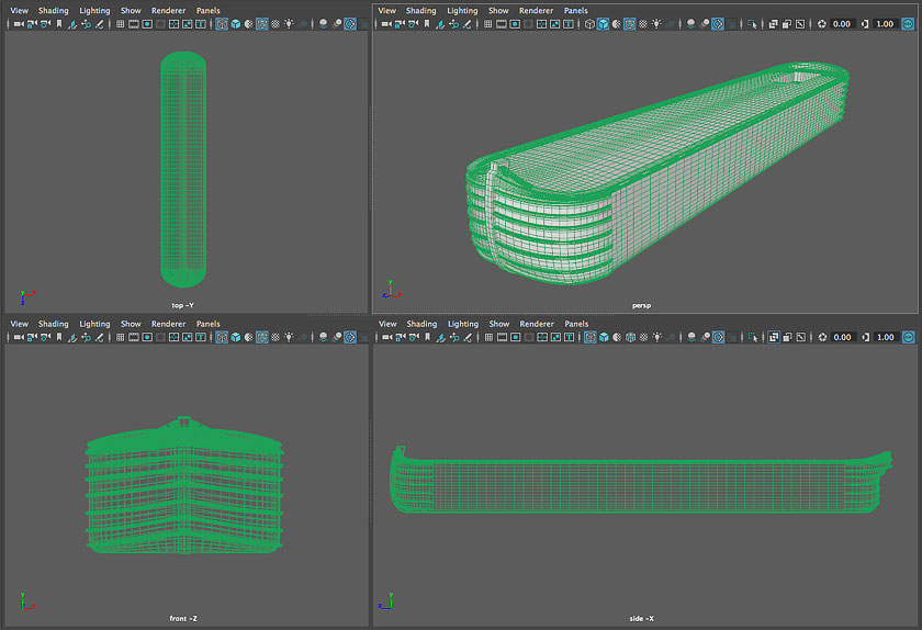
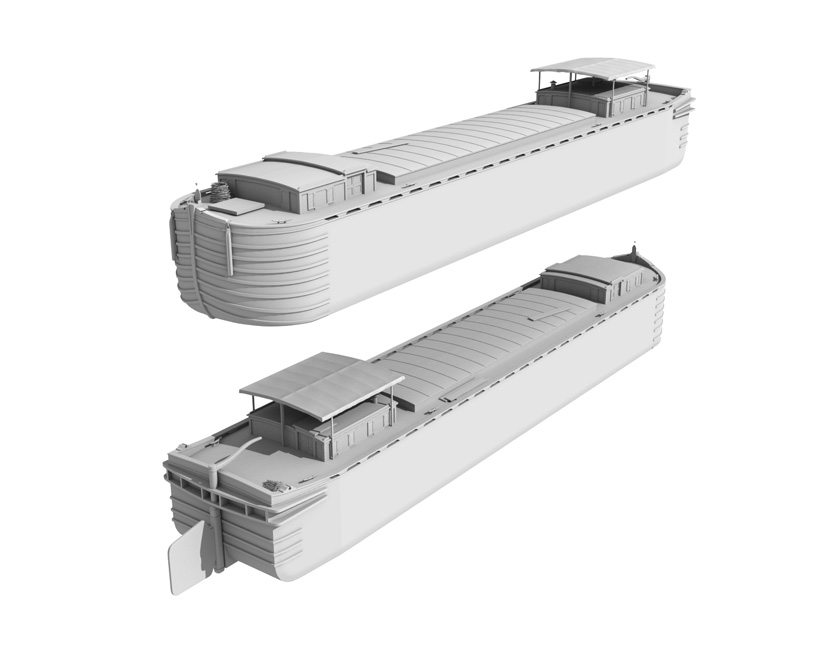
The Ashford’s hull is based on that of an 1870s-style laker.
Rebuilding the Ashford
My sources for the model are a high-resolution photo of the Ashford (provided by Bowling Green University), and Robert E. Hagar’s excellent drawings of an 1870s-era laker, held by the Chittenango Landing Canal Boat Museum.
The photograph isn’t the best quality, unfortunately, and some detail (especially behind the wheelhouse) is impossible to figure out. As usual, my rule is to leave out details rather than make them up. (The model will be seen at a distance and the stern won’t be prominent, anyway.)
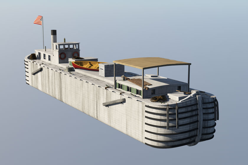
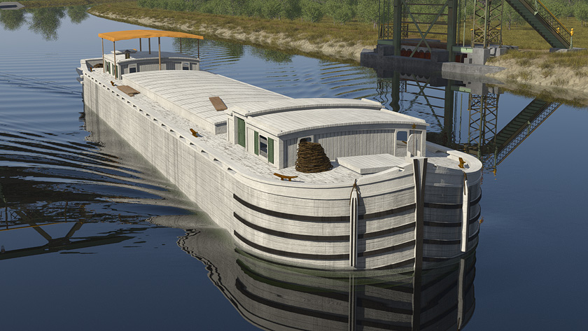
3D model of the Ashford, shaded and ready to be placed in the scene.
Once it’s finished the model is placed in the scene along with the three lakers. Our mighty fleet is at last under way.
The original laker model is modified to create three different boats, all based on the same basic hull shape.
Our Erie Canal laker model, shunted into digital dry dock last spring, will be expanded into a small fleet for our scene.
Of all the types of boats on the Erie Canal in 1916, the laker was the most common. Unpowered (or, in the jargon of the time, “unrigged”), it was the workhorse of the Erie Canal from the late 19th to the early 20th century. According to a Report on the Ship-Building Industry of the United States, published in 1884 by the U.S. Department of the Interior:
“The laker is a regularly framed boat, with perfectly flat bottom, square bilge, perpendicular sides, straight body, round bow and stern, and decked entirely over. It is made of oak and white pine . . . and it is 97 or 98 feet long, 17½ or 17⅔ beam, and 10 or 10½ feet in depth of side. . . .”
These boats . . . weigh from 65 to 72 tons, and carry 225 to 240 tons of cargo. They are usually painted white, and the stern is often profusely ornamented by a sign-painter, the name and home port being conspicuously painted in gilt and red and blue letters. About one-half of the boats on the Erie Canal are of this type. Being good for almost any service, these boats . . . are popularly used in forwarding grain from Buffalo and Oswego to New York city [sic] via the canal and the Hudson River.
In 1883 a newly built laker cost an average of $3,800, roughly equivalent to $95,000 today. It would see service for 10 to 15 years, perhaps longer if it were well maintained.
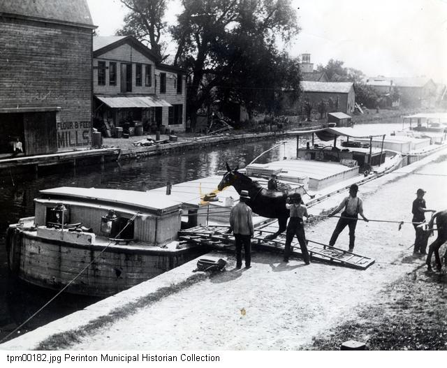
A mule is put aboard an Erie Canal laker in Fultonville, New York, around 1900 (Perinton Municipal Historian Collection).
For much of this period most canal boats were animal-powered. A team of three mules, walking along the canal’s towpath, could pull two fully loaded lakers lashed together. These doubleheaders would allow the owner to maximize his or her carrying capacity (and profit) with a minimum crew.
That crew, which often included family members, lived in the aft cabins. The animals were housed in the bow cabin or bowstable. Two teams of three mules were switched every six hours and kept the boats moving 24 hours a day. The speed limit was 4 miles per hour – a brisk walking pace – but most boats averaged less, covering the 360 miles between Buffalo and Albany in five to seven days.
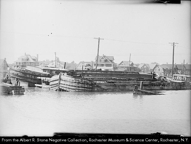
Abandoned canal boats choke the shallows of the Eastern Widewaters near downtown Rochester, New York, in the early 1900s. (Photo from the Albert R. Stone Negative Collection, Rochester Museum & Science Center.)
From 1880, steam-powered boats began to replace animal power. By 1916 – the date of our scene – the transition was virtually complete. Steel barges, another innovation, had made an appearance but their adoption would be interrupted by World War I, when all steel production would be diverted to the war effort.
So for the time being wooden lakers would be pushed and towed by wooden steamers. (There will be more about steamers in the next post.)
When they reached the end of their useful lives, wooden canal boats were often simply abandoned by their owners at “graveyards” where the canal was wide enough to accommodate their decaying wrecks.
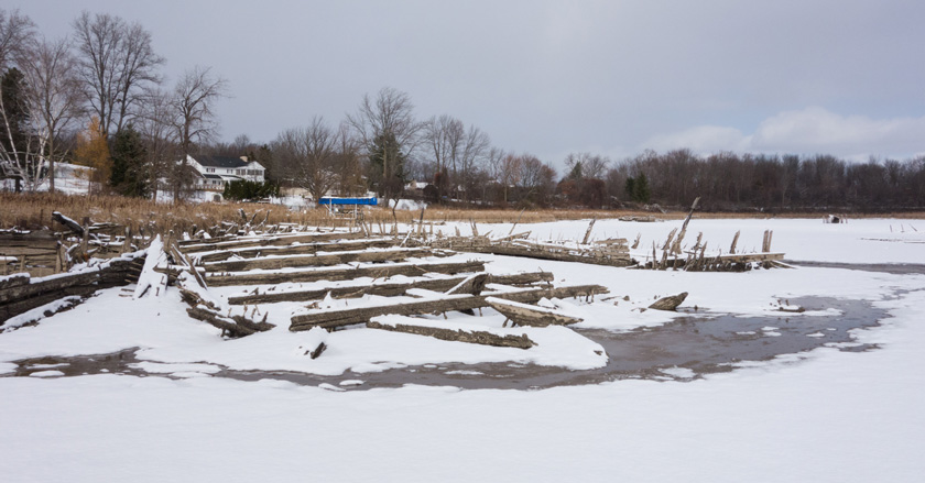
One old graveyard can still be seen along the canal in Pittsford, New York, where the sad, old frames are exposed when the canal is drained for winter. It’s amazing that they have survived for so long.
Remains of old scows lie on the bed of an old turning basin in Pittsford, New York.
Now that the terrain and major human-built objects are in place, it’s time to work on the scene’s natural elements: grass, wildflowers, weeds, and trees.
But before I could start modeling, I had to familiarize myself with the species that are native to this area – and would have been a hundred years ago. The National Wildlife Federation Field Guide to Trees of North America and the National Wildlife Federation Field Guide to Wildflowers of North America became my constant companions this fall. Both are densely packed with photos, maps and detailed descriptions of hundreds of species. Great for browsing at home as well as using in the field.
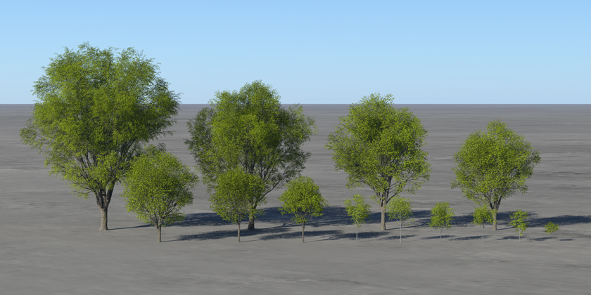
Assortment of sugar maple models, from 100-foot tall adults to saplings.
Sometimes it was possible to identify trees in historical photos. I settled on a mix of northern red oak, black walnut, and sugar maple. Some trees that are common here now, such as black locust and honey locust, were omitted because they are not native and I was not able to find out when they would have been introduced.
I collected and scanned leaves for identification and to use for modeling. Scanned leaves can be processed to create the different textures needed for 3D model construction.
Northern Red Oak leaf scan and processed images, from left: Diffuse (color), specular (reflection), and alpha (opacity).
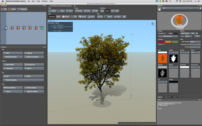
All of the foliage was created in SpeedTree, an industrial-strength tree and foliage 3D modeling tool that’s widely used in the motion picture and gaming industries. SpeedTree is one of those applications that does only one thing, but it does it very, very well. It has a short (but steep) learning curve. But once you begin to master it you can build just about anything.
SpeedTree workspace.
I used SpeedTree to make several models of each tree species, in various stages of growth. I also made about a half-dozen types of wildflowers, all of which should have been present in late September-early October 1916.
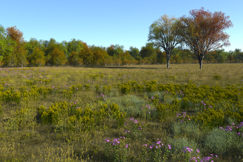
Test scene combines several species of trees, grass and wildflowers.
As a test, many of the species were mixed and placed in a new Terragen scene. Terragen shines when it comes to foliage because of its ability to place populations of thousands of models, its sophisticated noise and fractal functions that can be used to create natural-looking species distributions, and because of its renderer. This scene consists of billions of polygons, yet Terragen produced a rendering in a couple of hours without breaking a sweat. Impressive indeed.
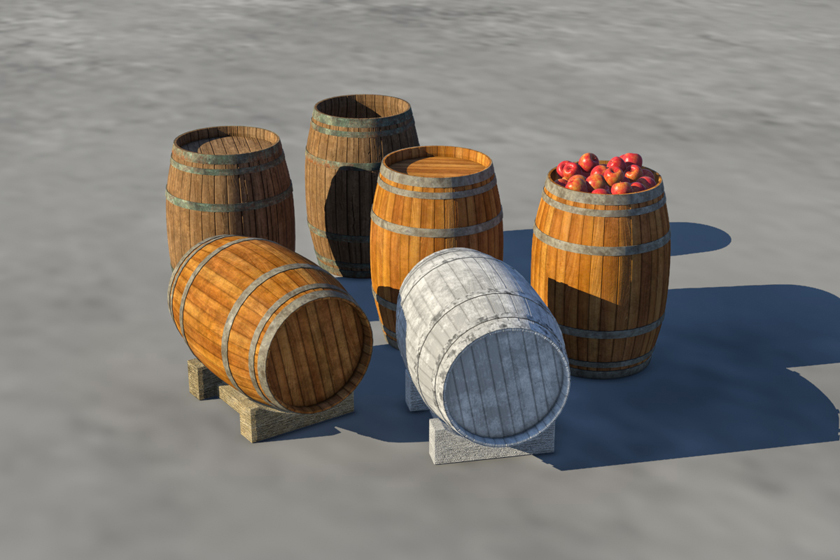
An assortment of barrels.
Besides foliage, I’ve also started building an assortment of small objects that will add detail to the scene. Here’s a selection of barrels that will be placed around the terminal area, on horse-drawn vehicles, and on the canal barges.
Working scene with foliage added.
Some care has to be taken in placing the trees in the working scene. It’s easy to overdo it. A hundred years ago this area would have been nearly clearcut to make space for farming and canal construction. In the decades since, unchecked second-growth woods have filled in much of the area depicted in our scene.
The new scene rendering shows the foliage in place with a scattering of cirrus clouds in the sky. It’s beginning to look like a picture.
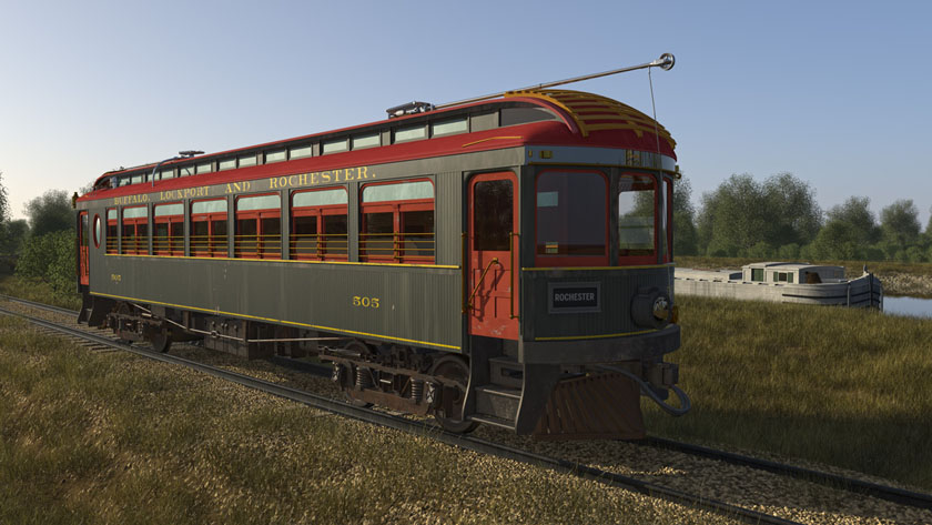
Completed model of Car 505, shaded and placed in the working Terragen scene.
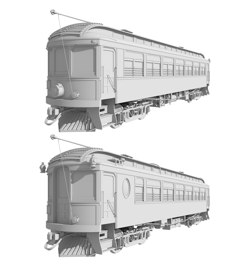
The exterior of the finished passenger car model is based on the original color scheme as delivered by the Cincinnati Car Company in 1909: Pullman Green body, Tuscan Red roof, Mandarin Red doors and sashes, gold lettering and stripes.
At some point the railway’s cars were repainted completely in red, but I haven’t been able to determine when that happened. But even if I learned that it happened before 1916, I’d be tempted to leave the original colors. They look pretty sharp.
A little rust on the trucks and undercarriage and a moderate amount of chipped paint and dust on the body has been added to show that the car has been in use for few years.
The model fits perfectly on the existing railway tracks in the Terragen scene. The image below shows the approximate final angle and framing of the scene with the car in place.
Wide-angle view shows the Terragen scene with the car in place.
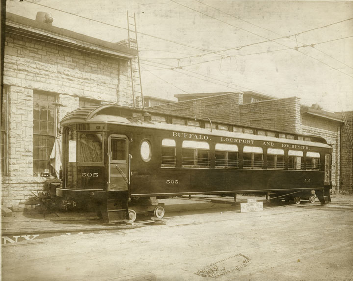
Car No. 505 stands in the yard at the Cincinnati Car Company before delivery to the BL&R railway. The trucks, trolleys, and electrical and brake systems are not yet installed. They will be purchased from other vendors and installed at the Rochester carshop. (Photo courtesy of the Indiana Historical Society)
The Buffalo, Lockport and Rochester electric interurban railway began service in late 1908 with 15 passenger motor cars built by the Niles Car and Manufacturing Company of Ohio. The BL&R had experienced financial trouble during construction but the future must have looked bright: Six more cars were ordered and put into service the following year.
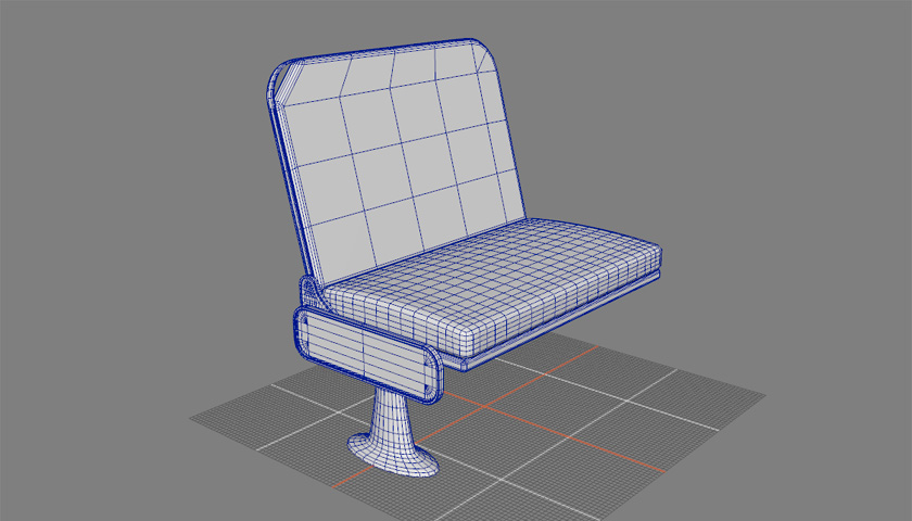
The new cars were built by the Cincinnati Car Company. Like the Niles cars these were high quality and comfortable, with mahogany interiors, plush seats, a separate smoking compartment, and room for 54 passengers.
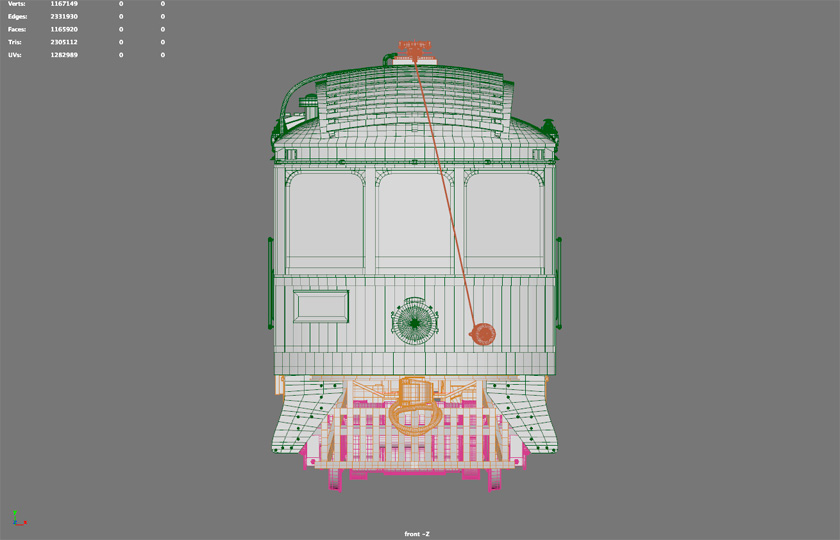
Z-axis view of the front of the traction car model.
The cars, constructed of wood and measuring 51 feet 6 inches in length, were double-ended and painted Pullman green with gold trim. They were powered by four 140-horsepower General Electric motors, originally geared for speeds up to 80 miles per hour, later reduced to 60. (There are stories of BL&R cars overtaking steam locomotives on the parallel New York Central Falls Line.)
They were numbered 500-505 and remained in service until the company, later reorganized as the Rochester, Lockport and Buffalo Railroad, went out of business in 1931.
Mounted on the rear of the car, marker lamps displayed red and green lights to indicate the car’s direction at night.
Because of the huge online “railfans” community, historical railway information is plentiful and easy to find. This is especially true for steam railways. Electric railway information is harder to come by but is available. The Electric Railroad Dictionary, published in 1911, is a rich resource and is available on Google Books and as a 1972 reprint.
The model for my scene is based on Car No. 505. The overall shape and dimensions are guided by a fine set of drawings by C. L. Richardson, published in William R. Gordon’s Rochester, Lockport and Buffalo R. R. in 1963. The Dictionary and historical photos help fill in the details.
The trolley pole will be mounted in this trolley base. Springs keep the wheel in contact with the underside of the overhead wire.
The model is more a collection of several models than a single piece. I’m not sure how much will appear in the final scene, or even what the viewing angle will be, so I’m erring on the side of too much detail.
Walkover Car Seat, No. 199-A, manufactured by Hale & Kilburn.
The most difficult part is the undercarriage, which is visually complex and difficult to see in photographs. But it’s possible to piece everything together with Richardson’s diagrams, the Dictionary, and a little patience.
In the process I learned a bit about how it all worked. The technology may have been crude, compared to today’s, but the engineers and designers were inventing a new form of transportation. The machines they built were ingenious, rugged, and beautiful. It’s interesting stuff.
Front and rear views of the completed model of Car No. 505. Shading will add color and more detail.
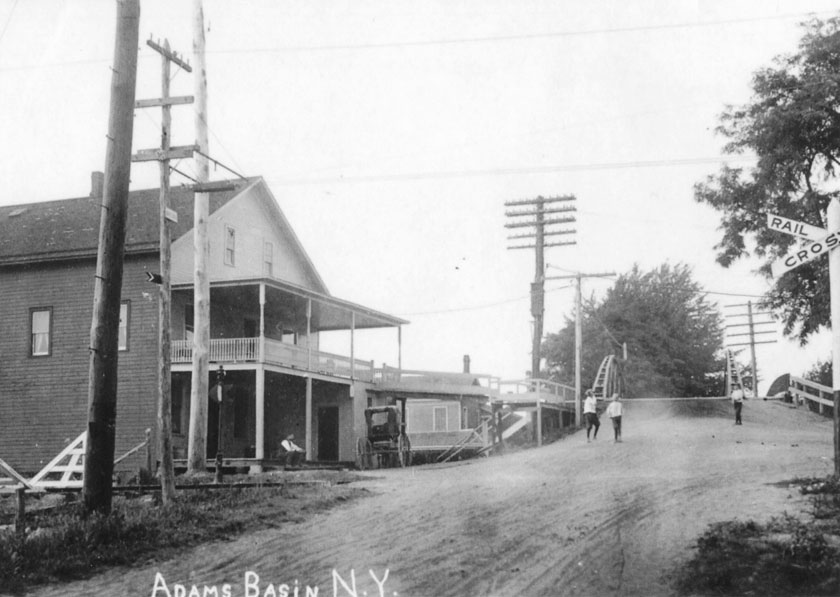
Postcard photo taken at Adams Basin between 1908 and 1910 shows the general store and old Erie Canal arch bridge. The new interurban railroad line crosses from left to right in the middle foreground with a warning sign at the extreme right. By 1913, a new lift bridge replaced the arch bridge.
Work on the bridge scene has taken a few unexpected twists and turns. But few have been as intriguing as this.
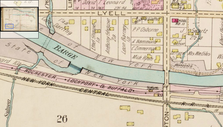
It turned up very early. While searching for information about the area around the bridge, I turned to contemporary plat maps digitized by the local library. The maps, which show property lines, buildings, bridges, roads and railroads, were published in 1902 and 1924. The first one is too early – the lift bridge was completed in 1913. Here is a section of the 1924 map.
1924 plat map of Adams Basin names each property and shows buildings, roads and railroads.
Everything in this map was familiar except for the line labeled “Rochester, Lockport & Buffalo.” I knew about the New York Central rail line, also labeled. But what was this?
A bit of digging quickly turned up more information. The RL&B was an electric interurban railway that connected Rochester with points west. Built in 1908, it was part of a web of interurbans that spread across western New York and the rest of the country.
At that time it wasn’t at all apparent that the automobile would be the transportation mode of the future. Roads were narrow and rutted, automobiles expensive and undependable. Railroads were the way to go. A mania spread as investors sank their fortunes into the burgeoning interurban industry.
But instead of buying stock in interurbans, ordinary people used their savings to buy Henry Ford’s new Model T. Roads were gradually improved and the automobile industry expanded. Interurban ridership declined and finally the bubble burst. Nearly all of the rail lines were defunct by the early 1930s.
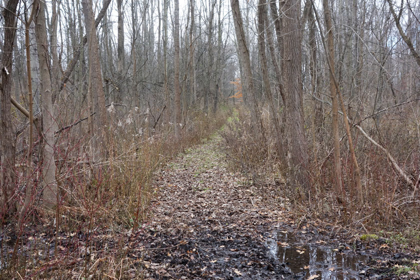
What’s left of the Buffalo, Lockport & Rochester right of way, next to the canal near Adams Basin.
The Buffalo, Lockport and Rochester Railroad had been sturdily built because it was expected to last for decades. Instead it was abandoned and literally ripped up: Cars, tracks, bridges, electric generating stations, and most passenger stations were simply scrapped.
The interurbans used traction cars, either singly or coupled in pairs, to carry passengers and some freight over standard gauge rails at speeds up to 80 miles per hour. These were not “trolleys.” They were light, high-speed electric railroads. Today, the fate of these innovative transportation systems seems to represent a missed opportunity.
Little survives. Traces of the overgrown right of way are barely visible from the air or on Google Earth. Some passenger stations have been preserved, and a derelict steel bridge crosses the canal in Rochester.
Photograph of a 1909 fire in Adams Basin inadvertently includes details of the interurban line, including the track and trolley wire.
Sometimes it’s impossible to pinpoint track and station locations. That’s the case with Adams Basin – the right of way vanishes in the immediate vicinity of the bridge. I feel like I’m chasing ghosts.
But it’s clear that the railroad must be in the scene. So, while the sleuthing continues, I’ve started modeling the traction car itself, starting with the “truck” or wheel assembly.
Model of a M.C.B. type Baldwin interurban railway truck. Two 140-horsepower General Electric motors (not shown) powered each truck. The traction car will include two of these.
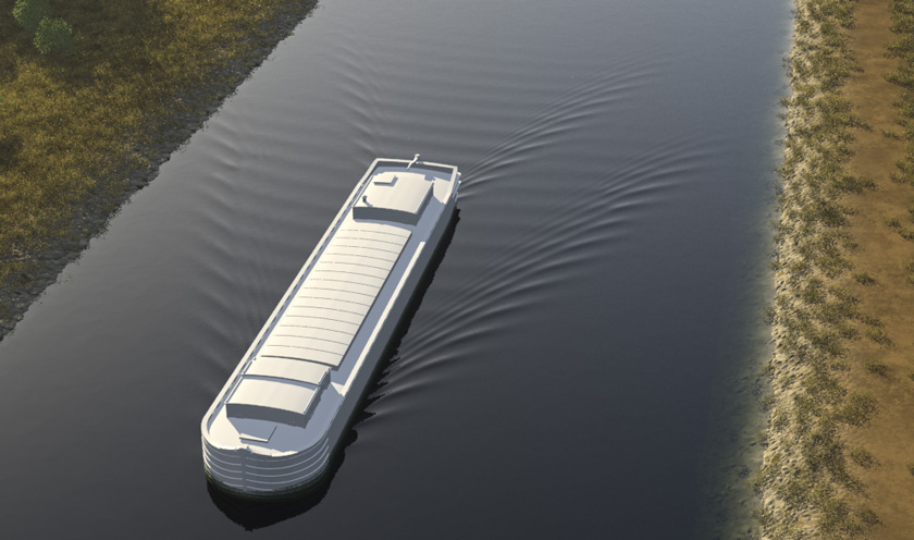
Test rendering of a partially completed laker model with a Kelvin wake pattern.
The canal scene is to be set in 1915 or 1916, a time of change for the Erie Canal. At enormous public expense, the canal was being upgraded to compete with the railroads. It was widened, all of the locks were replaced and enlarged, and dams and reservoirs were built to replace much of the original channel with “canalized” sections of the Mohawk River and other streams. The work began in 1909 and continued into 1917.
Wooden canal boats pulled by teams of horses or mules were being phased out. Eventually they would be replaced by large steel barges pulled by commercial tugboats. But change comes gradually at best and in 1917 all U.S. steel production was diverted to the war effort. So at this time there were still many traditional wooden Erie Canal boats in service. Some were animal-powered, some were towed by tugs. Some were combined into fleets of two or three boats and pushed and pulled by wooden steamers.
Traffic jam, 1905: Canal boats line up to pass through the Rochester weighlock. (Photo from the Albert R. Stone Negative Collection, Rochester Museum & Science Center.)
At this time the classic Erie Canal boat was the lakeboat or “laker,” which was around 98 feet long and had a cargo capacity of 240 tons. Lakers carried lumber, coal, gravel, and grain between Buffalo and Albany, or all the way to New York City via tug along the Hudson River.
Fore and aft views of the completed laker model.
My laker is based on plans drawn by Robert E. Hagar and now held by the Chittenango Landing Canal Boat Museum. It measure 97½ feet from bow to stern and has a draft of about 9 feet. In the traditional laker, the front cabin served as the stable (or “bowstable”) for the animal teams. Living quarters were in the stern cabin. It wasn’t unusual for entire families to live and work on board all season.
Completed laker model, shaded and in place on the canal.